Other Parts Discussed in Thread: THVD1500
Hi,
I would like to calculate the maximum number of connections, but I could not understand even after checking the following materials.
https://www.ti.com/lit/an/slla166/slla166.pdf
With above parts or RS-485 driver
・Number of nodes
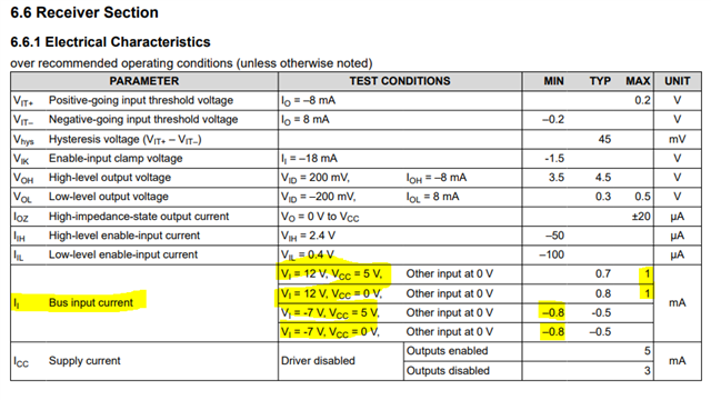
・Leak current
・Input resistance
Could you let me know what else you need? I would appreciate it if you could tell me the data, the calculation formula, or the numerical value of the data sheet.
Thanks,
Conor