This thread has been locked.

If you have a related question, please click the "Ask a related question" button in the top right corner. The newly created question will be automatically linked to this question.

MAX3221I does not generate the -5.5V on the RS232 TX

Other Parts Discussed in Thread: MAX3221

Hello all!

I want to ask you if you can help me with an issue we are facing. Right now we are using the MAX3221I to get information thorush a Harshman cable to communicate two units. But we are noticing that some of our basically does not generate the -5.5V on the RS232 TX on the non working board. And we just replace the unit for another one and it starts to work. Here are some pictures of the good and bad units.

Good Part.

Good Part

Bad Part.

Bad

Also we have the doubt about the marking difference. So, if anyone can help us, that will be awesome.

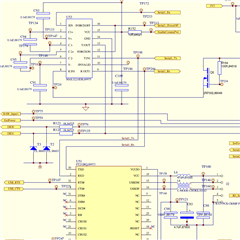
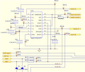
Here is a picture of the schematic.

thank you!!

  • What is the part number of T3?

    What is the measured V− voltage?

    Is this a single chip, or do some or all chip with the 'bad' marking fail?

  • Hi Rigoberto,

    Is the schematic correct in saying that you are using the DB package for the IC? 

    Could you answer a few questions for me please:

    1. What are the part numbers of T3 and T2? 

    2. Can you measure the voltage on the V- pin? This is the negative charge pump output.

    3. What is the VCC voltage - I am assuming its 5V - but please correct me if this isn't the case. 

    Best,

    Parker Dodson

  • Hello Clemens,

    - T3 is VC080514A300DP

    - For the faulty ICs, we were seeing around -640mV on the V- pin.

    - All the chips marked as "Bad" and with that .

  • Hello Parker,

    - T3 and T2 is VC080514A300DP

    - For the faulty ICs, we were seeing around -640mV on the V- pin

    - VCC voltage is 3.04V for us.

    Best regards,

  • −0.64 V looks like a diode drop. Apparently, there there is a diode between V− and GND.

    This sometimes happens when you use a unidirectional TVS diode for T3, but your varistor is OK.

    Does replacing the chip (not the unit) make it work? If yes, then the bad chip is not a MAX2331. If not, then the problem is a diode elsewhere on your board.

  • Hi Rigoberto,

    Could you please confirm that the package you are using is the DB package - as indicated by the schematic. 

    Best,

    Parker Dodson

  • Hello guys,

    Here is a more complete picture of the schematic.

    We have just realize that FTDI FT232RQ was replaced by the FT232RNQ. I think there could be a driven current from this new part, that maybe is burning the MB3221I and the FT232RNQ, because we notice we need to change both.

    But, what do you think?

    Thanks in advance,

    Best regards,

  • On an unpowered board, use a multimeter in continuity mode to check for the diode between V− and GND (in both directions). Unsolder components (MAX3221, T3, FTR232, etc.) until you find the culprit.

  • Rigoberto,

    Alright - please let me know if the package they are using is DB - if it is - then the parts are counterfeit as those markings don't match the DB package. 

    Best,

    Parker Dodson

  • Hello Parker,

    It is a PW package. Do the marks also pattern apply for this kind of Package?

    Best Reagrds,

  • Hi Rigoberto,

    Thank you for the confirmation - I just wanted to be sure that you had legitimate parts - the PW package is what the markings come back for - the schematic just has the incorrect orderable part number  - so no big issue there from any functional perspective.

    But I agree with Clemens analysis suggestion - checking to see if there is any diode connection could result in the inability to drive the -5V on the TX line. Since this is happening on two different chips - there could a similar cause for both issues. The V- not going to -5V however probably wouldn't directly cause a burn out on the other chip since the console pins are connected - not the bus. 

    Also what pins of the FTR232 are burning out - is it the TX/RX or is it around VCC? 

    Best,

    Parker Dodson

  • Hello Parker, Clemens,

    In fact, we found the solution. Seems that changing the C109 from 0.1uF to 1uF the communication worked again. Do you know if the current consumption has increased for the newer MAX3221 chips? Because changing the decoupling capacitor made the chip work in this case.

    Best regards,

  • Hi Rigoberto,

    I am glad that you were able to find a solution that worked - I don't see a lot of risk of a 1uF cap on the VCC pin however the powerline filtering will change a bit and if possible it probably wouldn't be a bad idea to have a 0.1uF in parallel for filtering reasons - but its probably not a huge issue regardless. 

    On the question did current consumption change - and its not as clear cut unfortunately. All versions of the device are bounded by the same max condition but they are tested unloaded - we don't spec ICC with a load - so the real answer is "maybe". However this specific issue hasn't shown up a lot in other uses of this part - so there could be a slightly higher expected load current for the negative swings in the system that requires a higher charge reservoir at VCC to be available or the power supply isn't able to provide the current it needs under negative swings so the additional cap helps provide charge in those cases. 

    You can also see that relatively small currents are going to cause rather large attenuation at the output for the negative swings:

    (this is for 3.3V VCC - but the fact is that the negative swing results in a higher output impedance regardless of VCC) 

    So ultimately it most likely one of these options:

    1. The Device itself requires more "under load" current -  requiring a higher decoupling cap.

    2. The Power supply isn't able to provide current necessary to drive the loads during negative swings 

    3. There is something on bus that is drawing more current than expected for RS-232 requiring the extra cap.

    4. Or a combination of them (which is what I am leaning towards as if it was part alone this issue would be more prevalent) 

    Please let me know if you have any other questions!

    Best,

    Parker Dodson

  • Hello Parker,

    Sure thank you. One last question.

    So, the chip could consume upto 60mA but we saw currents upto 136mA. That does not make sense. Does the max current consumption of the chip has changed?

    Thank you!

    Best regards,

  • Hi Rigoberto,

    Its possible - due to how we spec supply current on this device. We only spec no - load ICC - which is low and doesn't account for AC losses throughout the part - big reason we generally don't spec is due to the wide variety of "acceptable" data-rates and configurations so its hard to pin down to one - some devices may have a typical plot. So its one of these specifications that we don't directly spec - so it is possible for it to have gotten worse from the last device as its not characterized. 

    If you do see max spec violations as defined by our datasheet however please let us know as that could indicate damage from the device. Right now with the increase of supply current we don't necessarily suspect damage - but its not an ideal change. 

    Best,

    Parker Dodson