This thread has been locked.

If you have a related question, please click the "Ask a related question" button in the top right corner. The newly created question will be automatically linked to this question.

SN65HVD3088E: can not work at high baudrate

Part Number: SN65HVD3088E
Other Parts Discussed in Thread: THVD1420, THVD1520, , TVS0701, TPD1E10B09

Hi ,Experts

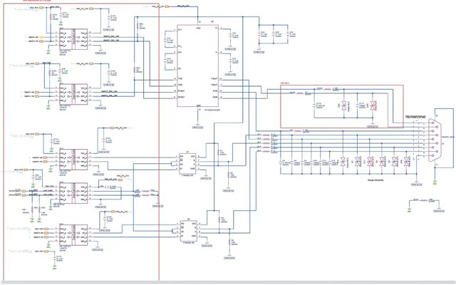
Here is a customer's RS485 project. when the customer use THVD1420, system can work normally at 10Mbps.

But if customer change THVD1420 to THVD1520, system will fail if baudrate is higher than approximately 4Mbps.

 if customer use SN65HVD3088E , system will fail if baudrate is higher than approximately 5Mbps.

Attachment is the test result.

Is there any thing i can do to improve the peformence?


Ti_THVD1420DR1520DRSN65HVD3088EDR.xlsx

Best regards

Nick

  • I do not see any termination resistors. Are they somewhere else? Can you show everything that is connected to the bus lines?

    Check the waveforms with an oscilloscope. I'd guess that the rising/falling edges are too slow because there is too much capacitance on the bus. (As far as I can see, the TVS diodes have 2000 pF. Check if removing them helps. There are TVS devices with lower capacitance like the TVS0701 or TPD1E10B09.)

  • Hi Nick,

    A couple points - that mainly mirror Clemens response.

    1. Can you show what the entire bus is connected to? I don't see termination resistors (which for how fast the SN65HVD3088E is - your bus doesn't have to be very long before you start having to consider transmission line effects - i.e. without termination resistors the SI of your bus could suffer - this may not be the only reason but it could be at least partially responsible. Also additional capacitance or protection diodes would be important.

    2. I do think the bus capacitance has a big role to play with diminished performance at higher speeds. It seems the diodes used are 2000pF - which is very high - for reference we measure differential rise and fall time (which is where we derive the devices data rate) with a load of 54 Ohms (eq. to 2 +/-10% 120 Ohm resistors in parallel to match proper RS-485 bus setup) with a 50pF differential cap. We do not test this with additional capacitance to ground - and you will experience some slew rate limiting due to the bus capacitance. With a lot of discrete capacitance right by the bus pins you will reduced performance with increased speed. 

    Please let me know on other bus connections but at the moment it seems that very capacitive diodes + the possibility of no termination (I am not sure how many nodes are in your system - and if the application is point to point then A/B should be terminated; I think since this is a multi-protocol RS-232/RS-485 it is point to point but please correct me if I am wrong) .

    If you can get a scope shot of the waveforms on the bus you should be able to see the output - I'd imagine it could be slew rate limited due to bus capacitance.

    Best,

    Parker Dodson

  • Hi Parker

    Thanks for your reply ,the customer test RS485 by connecting two same prototypes point to point. there is no termination resistor.

    I will ask the customer to add a termination resistor and do more test.

    Thanks

    Nick

  • There must be a termination resistor at every receiver. So if you are ever changing /UART2/3, then you need two resistors.

  • Hi Nick,

    Please let me know when you are able to get data after the termination to see how much improvement that has. Also if they could switch to less capacitive diodes that would also most likely provide a lot of benefit as well.

    Best,

    Parker Dodson

  •  Hi Parker

    A termination resistor did work, Thanks!

    Nick

  • Hi Nick,

    I am glad to hear it worked!

    Please let me know if you have any other questions!

    Best,

    Parker Dodson