Other Parts Discussed in Thread: TCA6424, TCA6416, TCA9535, TCA9534
Good evening,
On my design board , which is battery powered, I need to optimize the power consumption during sleep mode ( 40uA at 3.3V) , pull-up resistors on SDA and SCL are switched off.
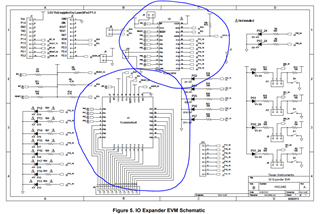
But I noticed that my eval board IO-EXPANDER-EVM is withdrawing 2.5mA of current ( I/O configured as input, both pull-up resistors R9 and R14 are removed as I am using pull-up resistors which can be power-cycled)
It seems that the IO Extender used on this eval baord doesn't go to standby mode as both SDA and SCL are not pulled-up .
I have done some research and I figured out that some IC like TCA 9534 and TCA 9535 doesn't need to have both SCL and SDA pulled-up to go to standby. can you confirm this ?
Is there any IO extender which can be configured in standby mode via software ?
many thanks for your guidance,
damon