This thread has been locked.

If you have a related question, please click the "Ask a related question" button in the top right corner. The newly created question will be automatically linked to this question.

TCA9554A: Is the Input Port Register a schmitt-trigger Inputs?

Part Number: TCA9554A

Hi all,

I would like to ask you two questions.

1) Is it a schmitt-trigger Inputs like SNx4 Series of logic IC?
2) What is rise/fall time of I/O port? Is there limit value?

I'm going to connect input capacitor for noise reduction.

I would like to know how many load capacitance of the input capacitor can be increased.

I would appreciate if you let me know the reference value.

Best Regards,

Ryusuke.

  • Hi Ryusuke,

    1) Is it a schmitt-trigger Inputs like SNx4 Series of logic IC?

    The i2c inputs monitor the voltage level of the input. An input high logic is considered 70% of VCC. An input low logic is considered 30% of VCC. In between 30% and 70% is undetermined by the I2C standard. These two values are far enough apart to act like a larger hysteresis so that noise doesn't accidently toggle the input of the edge cases. 

    2) What is rise/fall time of I/O port? Is there limit value?

    I'm going to connect input capacitor for noise reduction.

    I would like to know how many load capacitance of the input capacitor can be increased.

    I would appreciate if you let me know the reference value.

    No limit on the rise/fall time on the I/O port, it is voltage dependent on whether the flip-flop records a high or low logic value. 

    Input cap connection for noise reduction is fine, just make sure that it abides by the I2c standard. I2C has a maximum bus capacitance limit of 400pF (400pF on SCL and 400pF on SDA). Adding filter cap above 400pF is technically pushing the I2C bus out of spec and may cause issues with rise-time and the signal not being able to rise to a VIH before sampling which could result in data corruption. 

    I have attached an application note that describes how to select pull-up resistors based off of parameters such as bus cap, VOL, IOL, data rate, etc. Adjusting the amount of resistance and capacitance on the I2C directly affects the VOL and Rise-time seen on the I2C bus. 

    https://www.ti.com/lit/an/slva689/slva689.pdf?ts=1695910728074&ref_url=https%253A%252F%252Fwww.google.com%252F

    Regards,

    Tyler

  • Hi Tyler,

    Thank you for your reply.

    I understood the question of 2).

    Let me add to question 1).

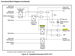
    the device has the Input Port Register.

    1) Is the Input Port Register a schmitt-trigger Inputs?

    The general logicIC is 0.7×Vcc, but this is 0.8×Vcc when Vcc is 3.3V.

    So I thought it might be a schmitt-trigger input.

    Best Regards,

    Ryusuke.

  • Hi Ryusuke,

    From a previous thread, I was able to gather that the CMOS inputs on the p-port sides have about 100mV of hysteresis built in, but this is not listed explicitly in the datasheet. 

    I2C signals do not have schmitt trigger inputs. 

    Regards,

    Tyler

  • Hi Tyler,

    I understand it's not regulated.

    I would like to know make reference to it.

    Please let me know your opinion.

    Best Regards,

    Ryusuke

  • Hi Ryusuke,

    What do you mean by this statement:

    I would like to know make reference to it.

    Are you talking about a datasheet change? 

    Regards,

    Tyler

  • Hi Tyler,

    I'm sorry I didn't make it clear enough.

    I just want to use it as a reference when I design circuit.

    I would like to hear your opinion even if the information is not regulated in the datasheet.

    Best Regards,

    Ryusuke

  • Hi Ryusuke,

    Regardless of hysteresis, the input voltage is characterized to I2C standards either VIL = 30% of VCC or VIH = 70% or 80% of VCC. There is a large margin existing between VIL and VIH, so I wouldn't expect the addition of noise to toggle an input between high and low logics making the data corrupt. 

    For example...

    Once a low logic input is registered, it doesn't become a high logic input until 70% of VCC in the internal input port register. You can be assured by the datasheet that once the input reaches 70% of VCC, you would read a logic HIGH (1) in the input port register. Conversely, when the logic high signal on the input begins to fall, the data inside the input port register will only change once the input has fallen below 30% VCC. 

    This basically acts like hysteresis in a sense. 

    Regards,

    Tyler