This thread has been locked.

If you have a related question, please click the "Ask a related question" button in the top right corner. The newly created question will be automatically linked to this question.

TSD05C: GPIO Protection of MCU with 5.5V AMR

Part Number: TSD05C
Other Parts Discussed in Thread: AM26C31, TCA9803, TLV9062, TMP61-Q1, ESDS314, ESDS312

Hello,

We need to protect GPIO pins from long cables (Inductive Proximity sensor signal) coming from around motors in industrial environment.

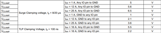
Apart from using Digital Isolator, we are considering a lower cost & relatively balanced risk solution such as TSD05C for clamping the surge (61000-4-5 Class 2) & EFTs (61000-4-4 Class 4)

I am unsure about:

  1. Higher clamping voltage of the TSD05C which is +14V
  2. Higher breakdown voltage of the TSD05C which is +/-8V

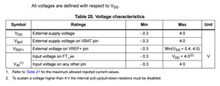
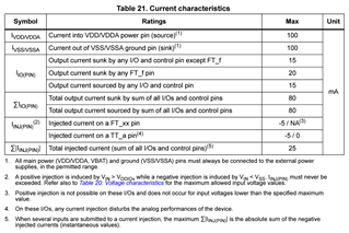
Both of the above key voltage levels are well above the AMR of the MCU GPIO pins. Now I do understand that the AMR is rated for constant DC voltage & transient we might be able to have a slightly higher voltage - however I am unsure how high can we work with, specifically will this TSD05C be sufficient for a typical MCU GPIO protection given it's Clamping voltage & the Breakdown voltages?

Kindly suggest, if not which other protection can we use?

  • Hi Shreeneet,

    Could you please provide the GPN of the MCU you are using? This will help me find a device suitable for your application.

    In addition, could you please provide the speed of data being transferred on the GPIO pins? 

    Best Regards,

    Josh Prushing

  • Hello ,

    The maximum data transfer are for two types:

    1. 2kHz for Encoder input signal
    2. upto 400kHz for I2C as well as for the SPI data lines

    Both of these cables shall be about 3-5m typical, For SPI we have used AM26C31/32 for converting single ended to differential, for I2C we are using TCA9803 as buffer & RTA & plan to increase the system reliability & robustness by ensuring these devices apart from the MCU GPIO pins are safe or relatively safe.

    Apart from these, the cables shall be CAT6e cables with proper grounding at one end.

    Can you kindly explain what is that you mean by GPN of the MCU? The MCU we are using is STM32G0 series with 3.3V Supply & the pins are 5V tolerant pins as found on all the STM32.

    Sharing for your reference:

  • Hi Shreeneet,

    Thank you for providing all of that information!

    By GPN, I meant the part number of the MCU, which you mentioned is the STM32G0 series.

    When you mentioned the AMR earlier, did you mean that the input pins have a constant voltage on the input, or that is just how the measurement is done? In addition, could you please share the AMR values of the GPIO pins? Or are these values the absolute maximums listed in table 20 of the datasheet?

    Apologies if there is any confusion!

    Best Regards,

    Josh Prushing

  • Hello Josh,

    Sure, the MCU is STM32G0B0RET6.

    No, the constant voltage shall be 3.3V, anything above 3.3V is transient event.

    Yes, the table 20 & 21 I have shared are the AMR values for the GPIO.

    Our use case has essentially 2 needs direct GPIO (upto 2kHz) & Peripheral Components (upto 400kHz) connecting to GPIO listing them below for your reference:

    • We need to secure the Digital inputs GPIO pins (direct)
    • Analog input pin from 5.5V TMP61-Q1 goes to TLV9062 in attenuator buffer configuration- needs to be protected at both the ends TMP61-Q1 side as well as the TLV9062 which is interfaced with Analog Input (Peripheral)
    • We need to secure AM26C31/32 field cable side pins (Peripheral)
    • We need to secure TCA9803 field cable side pins (Peripheral)
    • Power supply input needs protecting the LDO (that converts 5V into 3.3V & accepts a maximum of 5.5V at it’s inputs)

    Ideally we need a TVS Diode with clamping voltage around 5.5 to 7V assuming the 61000-4-4 & 4-5 surges are transients with micro-second duration.

    For 61000-4-5 Surge protection we need Class 3 or atleast Class 2 protection with a minimum of 25A current rating.

    For 61000-4-4 EFTs we need Class 4 protection.

    Let me know if these inputs clarify the use case.

  • Hi Shreeneet,

    Our devices that best suits this are our ESDS314 (4 channel) or ESDS312 (2 channel). These devices meet the 61000-4-4/5 test requirements described above, as well as the clamping voltage requirements. Please see the image below comparing the specifications:

    Although the clamping voltages are listed as being different, these are simply at differing TLP values. Please see this excerpt from the datasheet:

    Please note that these devices use the same datasheet, as the only difference is the pin function. 

    Please let me know if you have any additional questions!

    Best Regards,

    Josh Prushing

  • Hello Josh,

    Thank you for the suggestion & the inputs.

    Do you think we should consider a bi-directional TVS diodes? How do we make this decision of uni/bi-directional diode selections?

    Though the voltage levels shall always be uni-polar, can you share some guidance on this aspect of TVS diode selection?

    Most helpful shall be a suggestion of two for the bi-directional TVS diode for the given use case as alternatives for the uni-directional ESD314/312.

    Regards.

  • Hi Shreeneet,

    If there is no threat of negative voltage occurring on these pins, Uni-directional will be able to protect against the expected transients. If there is potential for negative voltage, a Bi-directional diode will be needed to properly protect the system. If you would like more information on this, you can find more information in our Design Considerations for System-Level ESD Circuit Protection guide on pages 3-4 under the section labeled "How a TVS protects a system against ESD events".

    Please let me know if I can answer anything else for you!

    Best Regards,

    Josh Prushing

  • Hello ,

    Thank you for sharing the article, our usecase requires bi-directional protection, I am unable to find anything in bi-directional available from TI, can you help us confirm once?

    Regards

  • Hi Shreeneet, 

    You can connect the pins of both ESDS312 and ESDS314 in a way to make the device function as a bi-directional device, but you will have a reduced channel count. For ESDS312, if you connect IO1 to the line you are trying to protect and IO2 to ground, this will act as a bi-directional device. For ESDS314, you can do the same, following the same format of IO1 and IO3 connected to the lines needing protection, and IO2 and IO4 connected to ground. This will lead ESDS312 to be a one channel bi-directional device, while ESDS314 will be a 2 channel device.

    Apart from doing this, TI does not have bi-directional devices that meet the above specifications.

    Best Regards,

    Josh Prushing

  • Hello Josh,

    Is TSD05C suitable for our use case? As it offers the required Bi-directional as well as higher Surge protection. What I am reaching out to the E2E community is to confirm my doubts about:

    • Is AMR ratings of 6.5V & a clamping voltage of 9V an acceptable combination for protection?

    What I understand is that AMR ratings are given for constant input & not transient voltages, so can we assume 9V Clamping on TLPs can be acceptable for securing the inputs of 5V tolerant GPIOs on STM32 MCUs?

  • Hi Shreeneet,

    Unfortunately, I cannot confirm if TSD05C can be used in this case. Clamping voltage is a transient specification, meaning any ESD diode's performance is going to be based on its transient response instead of a constant response. You are correct that there is some allowance between transient and constant voltage, but this tolerance is not clear for this device. 

    In order to obtain confidence in TSD05C's ability to protect against the 6.5V constant input, performing bench testing would be the best solution. If you would like to order free samples to conduct this testing, you can do that using this link and scrolling to the "Ordering & Quality" section and clicking the "Request Sample" button.

    Please let me know if you have any more questions!

    Best Regards,

    Josh Prushing