Part Number: TCAN4550
Hello!
I am trying to rework the included Demo code for the TCAN4550 for my microcontroller setup, the STM32. In order to test my implementation, I am attempting to read the Device ID register. However, whenever I try to read I always get a value of 0 out. I'm sure this could mean that my SPI implementation is incorrect, but I also want to post my general setup to see if I am missing anything. Also, for reference, I am using the TCAN BOOST module and interfacing it with a STM32 Nucleo board.
SPI Parameters (for the MCU):
Clock freq: 10.5MBit/s
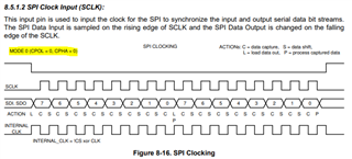
CPOL = 0, CPHA = 1 Edge
Frame format: Motorola MSB First, Data size: 8 bits,. Full duplex master
In my code, the first thing that I do is set the nCS pin high before pulsing the RST pin on the TCAN (I am using the GPIO_RST pin on the BOOST module). After pulsing it, I find that the VCCOUT and nINT LEDs are active on the BOOST module. I'm sure this means that the TCAN is in the standby state? I'm not sure why the nINT LED is on, and I am unable to read the device interrupt register anyways. After pulsing RST, I try to read the Device ID register with no luck.
I am powering the BOOST module through the DC barrel jack with 12V. I am also only connecting the SPI interface, GND, and RST pins to the TCAN board. Here is my setup for performing the SPI functions.
void SPI_WRITE_32(SPI_HandleTypeDef *hspi, uint16_t address, uint8_t num_words, uint32_t pData)
{
    SPI_WRITE_BURST_START(hspi, address, num_words, pData);
    SPI_WRITE_BURST_WRITE(hspi, address, num_words, pData);
    SPI_WRITE_BURST_END();
}

uint32_t
SPI_READ_32(SPI_HandleTypeDef *hspi, uint16_t address)
{
    uint32_t returnData;

    SPI_READ_BURST_START(hspi, address, 1);
    returnData = SPI_READ_BURST_READ(hspi, address);
    SPI_READ_BURST_END();

    return returnData;
}

/*
 * @brief Burst write start
 *
 * The SPI transaction contains 3 parts: the header (start), the payload, and the end of data (end)
 * This function is the start, where the register address and number of words are transmitted
 *
 * @param address A 16-bit address of the destination register
 * @param words The number of 4-byte words that will be transferred. 0 = 256 words
 */
void SPI_WRITE_BURST_START(SPI_HandleTypeDef *hspi, uint16_t address, uint8_t num_words, uint32_t pData)
{

    // Prepare the data for SPI transmission
	// Prepare the data for SPI transmission
	uint16_t opcodeAndHighAddress = (WRITE_OPCODE << 8) | ((address >> 8) & 0xFF);
	uint16_t lowAddressAndNumWords = ((address & 0xFF) << 8) | num_words;

	// Create a 32-bit value from the prepared data
	uint32_t combinedValue = ((uint32_t)opcodeAndHighAddress << 16) | lowAddressAndNumWords;

	// Extract individual 8-bit values
	uint8_t msb = (combinedValue >> 24) & 0xFF; // Most significant byte
	uint8_t byte2 = (combinedValue >> 16) & 0xFF;
	uint8_t byte1 = (combinedValue >> 8) & 0xFF;
	uint8_t lsb = combinedValue & 0xFF;         // Least significant byte

    // set CS gpio low
    HAL_GPIO_WritePin(GPIOC, nCS_Pin, GPIO_PIN_RESET);

    // Send the first 16-bit SPI packet (opcode and top 8 bits of address)
    HAL_StatusTypeDef status = HAL_SPI_Transmit(hspi, &msb, sizeof(byte3), HAL_MAX_DELAY);
    HAL_SPI_Transmit(hspi, &byte2, sizeof(byte2), HAL_MAX_DELAY);
    HAL_SPI_Transmit(hspi, &byte1, sizeof(byte1), HAL_MAX_DELAY);
    HAL_SPI_Transmit(hspi, &lsb, sizeof(byte0), HAL_MAX_DELAY);

}

/*
 * @brief Burst write
 *
 * The SPI transaction contains 3 parts: the header (start), the payload, and the end of data (end)
 * This function writes a single word at a time
 *
 * @param data A 32-bit word of data to write to the destination register
 */
void SPI_WRITE_BURST_WRITE(SPI_HandleTypeDef *hspi, uint8_t num_words, uint16_t address, uint32_t pData)
{
	uint8_t byte3 = (pData >> 24) & 0xFF; // Most significant byte
	uint8_t byte2 = (pData >> 16) & 0xFF;
	uint8_t byte1 = (pData >> 8) & 0xFF;
	uint8_t byte0 = pData & 0xFF;          // Least significant byte

	// Send the first 16-bit SPI packet (opcode and top 8 bits of address)
	HAL_StatusTypeDef status = HAL_SPI_Transmit(hspi, &byte3, sizeof(byte3), HAL_MAX_DELAY);
	HAL_SPI_Transmit(hspi, &byte2, sizeof(byte2), HAL_MAX_DELAY);
	HAL_SPI_Transmit(hspi, &byte1, sizeof(byte1), HAL_MAX_DELAY);
	HAL_SPI_Transmit(hspi, &byte0, sizeof(byte0), HAL_MAX_DELAY);

}

/*
 * @brief Burst write end
 *
 * The SPI transaction contains 3 parts: the header (start), the payload, and the end of data (end)
 * This function ends the burst transaction by pulling nCS high
 */
void SPI_WRITE_BURST_END(void)
{
// set CS gpio high again to indicate the end of the burst
    HAL_GPIO_WritePin(GPIOC, nCS_Pin, GPIO_PIN_SET);
}

/*
 * @brief Burst read start
 *
 * The SPI transaction contains 3 parts: the header (start), the payload, and the end of data (end)
 * This function is the start, where the register address and number of words are transmitted
 *
 * @param address A 16-bit start address to begin the burst read
 * @param words The number of 4-byte words that will be transferred. 0 = 256 words
 */
void SPI_READ_BURST_START(SPI_HandleTypeDef *hspi, uint16_t address, uint8_t words)
{

	// Prepare the data for SPI transmission
	uint16_t opcodeAndHighAddress = (WRITE_OPCODE << 8) | ((address >> 8) & 0xFF);
	uint16_t lowAddressAndNumWords = ((address & 0xFF) << 8) | num_words;

	// Create a 32-bit value from the prepared data
	uint32_t combinedValue = ((uint32_t)opcodeAndHighAddress << 16) | lowAddressAndNumWords;

	// Extract individual 8-bit values
	uint8_t msb = (combinedValue >> 24) & 0xFF; // Most significant byte
	uint8_t byte2 = (combinedValue >> 16) & 0xFF;
	uint8_t byte1 = (combinedValue >> 8) & 0xFF;
	uint8_t lsb = combinedValue & 0xFF;         // Least significant byte

    // Set the CS low to start the transaction
    HAL_GPIO_WritePin(GPIOC, nCS_Pin, GPIO_PIN_RESET);

           // Send the first 16-bit SPI packet (opcode and top 8 bits of address)
    HAL_StatusTypeDef status = HAL_SPI_Transmit(hspi, &msb, sizeof(byte3), HAL_MAX_DELAY);
    HAL_SPI_Transmit(hspi, &byte2, sizeof(byte2), HAL_MAX_DELAY);
    HAL_SPI_Transmit(hspi, &byte1, sizeof(byte1), HAL_MAX_DELAY);
    HAL_SPI_Transmit(hspi, &lsb, sizeof(byte0), HAL_MAX_DELAY);

    // Send the 16-bit address
    // Send the first 16-bit SPI packet (opcode and top 8 bits of address)
    // Handle an SPI transmit error by trying again
    if (status != HAL_OK)
    {
        SPI_READ_ERR_HANDLER(hspi, address);
    }
}

/*
 * @brief Burst read start
 *
 * The SPI transaction contains 3 parts: the header (start), the payload, and the end of data (end)
 * This function where each word of data is read from the TCAN4x5x
 *
 * @return A 32-bit single data word that is read at a time
 */
uint32_t
SPI_READ_BURST_READ(SPI_HandleTypeDef *hspi, uint16_t address)
{
	uint8_t readData0;
	uint8_t readData1;
	uint8_t readData2;
	uint8_t readData3;
	uint32_t returnData;

	HAL_SPI_Receive (hspi, &readData0, sizeof(readData0), HAL_MAX_DELAY);
	HAL_SPI_Receive (hspi, &readData1, sizeof(readData1), HAL_MAX_DELAY);
	HAL_SPI_Receive (hspi, &readData2, sizeof(readData2), HAL_MAX_DELAY);
	HAL_SPI_Receive (hspi, &readData3, sizeof(readData3), HAL_MAX_DELAY);

	returnData = (((uint32_t)readData0) << 24) | (((uint32_t)readData1 << 16)) | (((uint32_t)readData2) << 8) | readData3;

	return returnData;

}

/*
 * @brief Burst write end
 *
 * The SPI transaction contains 3 parts: the header (start), the payload, and the end of data (end)
 * This function ends the burst transaction by pulling nCS high
 */
void SPI_READ_BURST_END(void)
{
    // set CS gpio high
    HAL_GPIO_WritePin(GPIOC, nCS_Pin, GPIO_PIN_SET);
}
And I am calling the SPI_READ_32 as such:
uint32_t readvalue;
TCAN4x5x_Device_ClearSPIERR(&hspi2);
readvalue = SPI_READ_32(&hspi2, REG_SPI_DEVICE_ID1);
Does anyone have intuition on what may be going wrong?
Thank you in advance