This thread has been locked.

If you have a related question, please click the "Ask a related question" button in the top right corner. The newly created question will be automatically linked to this question.

SN65HVD234: Part marking VP234 12M JMN7 Lower differential voltages and does not receive car CAN.

Part Number: SN65HVD234
Other Parts Discussed in Thread: TCAN334,

Hi all

We ran into an issue with what looks like a CAN transceiver batch that is bad. My question is are we missing something and using the CAN IC wrong or did we get a bad batch?  
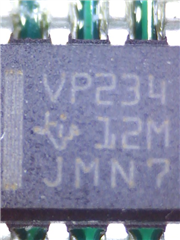


When we do a loopback test between two CAN transceivers we get a lower differential voltage and we do not know why.

The same test done with previous PCB shows a higher differential voltage and is able to pick up the CAN of a car. 

When we swap the "Bad IC" with a good one it works as expected. 

See below example of a "bad IC" left and a good one right. 


A few things to note. 
1) The recessive state CAN-H/CAN-L is ~2V versus ~2.3V
2) The differential voltage is ~1.3V versus 2.5V
3) The left side seems to have some ringing but due to the differential signal it does not seem to affect the results that much (blue line)
4) The setup is the same between test. 

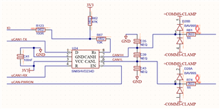
Below is the schematic. The "bad IC" would also start to pick up vehicle CAN when we pull the IO line low. I think I am missing something important in the datasheet. The good IC works with IO floating so low power state? 


Any assistance would be great. Thank you. 

  • Hi Albert,

    Thanks for bringing your question to E2E.

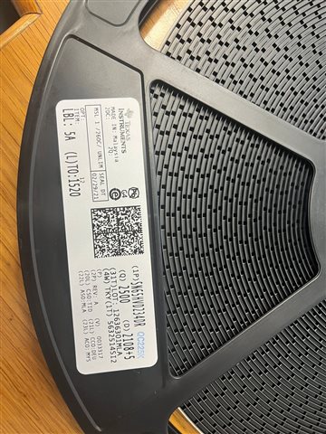
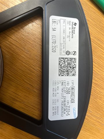
    Would you be able to share the lot code and data that was included on the shipment of "bad IC" units? I can't find the lot in our system based on the markings shown in the image you shared. 

    The recessive bias for this device is designed to be most compatible with 5V CAN systems and is nominally 2.3V when idle (may be higher due to other 5V devices' bias). A recessive state common mode of 2.0V is low and unexpected for this device. This would be behavior more expected by a 3.3V CAN transceiver that is designed for homogeneous 3.3V CAN networks such as the TCAN334 (which still has a higher bias of 1.85V nominal, which could be pulled up the 2.0V by other 5V devices). Such a device would also experience more ringing in the common mode as the bias settles between dominant and recessive levels. 

    Below is the schematic. The "bad IC" would also start to pick up vehicle CAN when we pull the IO line low. I think I am missing something important in the datasheet. The good IC works with IO floating so low power state? 

    Which device pin is "IO" in this case? The SN65HVD234 requires Vcc to be present in order to drive or receive CAN data. The EN pin also needs to be high in order for the transmitter and receiver to function. The Rs pin only impacts the driver so the transceiver may still receive CAN communication when this pin is high (listen only mode) or low (slope control mode). 

    Regards, 
    Eric Schott  

  • Hi Eric 

    The IO is the Rs pin. It can be high with a 57K (10K + 47K) pullup or pulled low by IO with a 10K. The Vcc is at 3.3V and I confirmed that it looks clean and stable. The EN pin is also enabled. 

    Do you know what the speed is of the unit in listen only mode ? So if we have the 57K (10K + 47K) pullup.

    Please see below the lot details for the reals that we suspect. 


    Thank you 
    Regards
    Albert

  • Hi Albert,

    I'm sorry to say that these are likely counterfeit devices. Please reach out to the distributor you ordered these parts from to track their source. If they are on our list of approved vendors, please fill out the counterfeit device form and forward it to our customer supply center. 

    https://www.ti.com/ordering-resources/distributors.html 

    https://www.ti.com/support-quality/quality-policies-procedures/anti-counterfeit.html 

    Regards,
    Eric Schott