Other Parts Discussed in Thread: TCAN334,
Hi all
We ran into an issue with what looks like a CAN transceiver batch that is bad. My question is are we missing something and using the CAN IC wrong or did we get a bad batch? 
When we do a loopback test between two CAN transceivers we get a lower differential voltage and we do not know why.
The same test done with previous PCB shows a higher differential voltage and is able to pick up the CAN of a car.
When we swap the "Bad IC" with a good one it works as expected.
See below example of a "bad IC" left and a good one right. 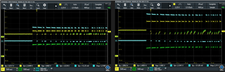
A few things to note.
1) The recessive state CAN-H/CAN-L is ~2V versus ~2.3V
2) The differential voltage is ~1.3V versus 2.5V
3) The left side seems to have some ringing but due to the differential signal it does not seem to affect the results that much (blue line)
4) The setup is the same between test.
Below is the schematic. The "bad IC" would also start to pick up vehicle CAN when we pull the IO line low. I think I am missing something important in the datasheet. The good IC works with IO floating so low power state? 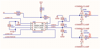
Any assistance would be great. Thank you.