This thread has been locked.

If you have a related question, please click the "Ask a related question" button in the top right corner. The newly created question will be automatically linked to this question.

AM26C31: some AM26C31 is not producing the output properly

Part Number: AM26C31
Other Parts Discussed in Thread: AM26LV31E, AM2631

hi,

We are using an incremental encoder in our product.

The encoder supplier is using AM26C31.

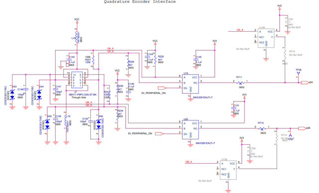
In our motion control board, the  interface schematic to the encoder is shown below. 

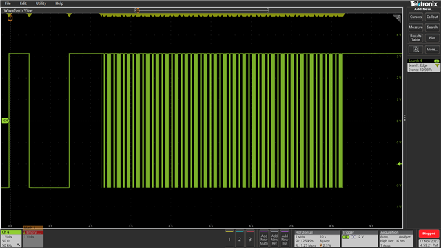
The good encoder counts for a fixed distance travel is given below (QA, QB)  . It gives 50.456K rising edges if we see the events in right edge of the screen shot..

Some faulty units we are seeing encoder pulses missing 

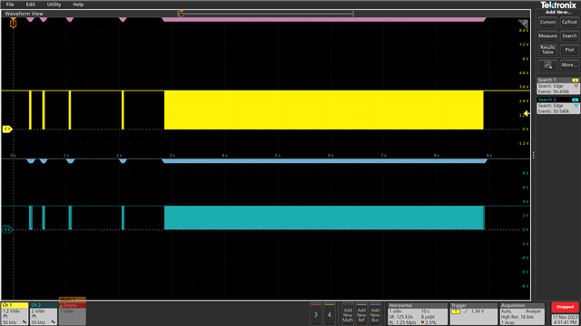
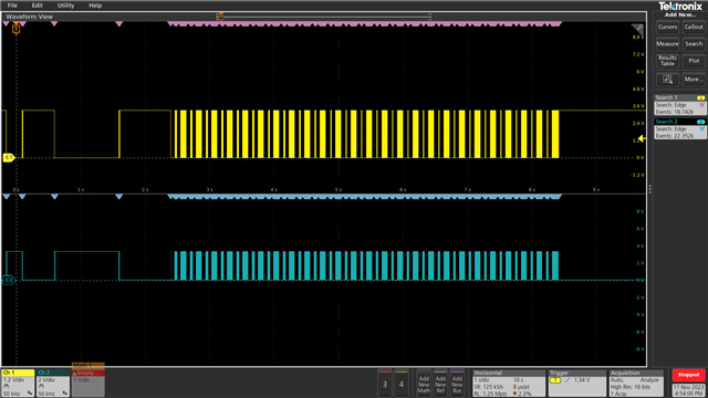
For the faulty encoder, the screen shot is given below. It gives only 18.742K rising edges if we see the events in right edge of the screen shot.. But the motor is moved to the same distance and confirmed it using laser distance sensor.


So it is clear that the IC AM26C31 in the encoder module is not behaving.

This could be due to long term failure or some thing as the units were running properly and it had developed these issues now.

The receiver interface circuit above is right. Is there anything that could harm AM26C31?

Your inputs are valuable as the production is stuck due to this issue. 

regards

Subramani

  • Hi Subramani,

    So I am not sure if you attached the wrong schematic - but the part number is different and the AM26C31 is a 5V part - so it won't work at 3.3V if this same setup is used with the AM26C31 (i.e. the IC. U19 and U20 are each channels of the AM2631) The appropriate 3.3V option is the AM26LV31E which essentially is just a 3.3V version of the current device. Using the device at 3.3V could have issues in operation - so that would be my main concern. 

    Please let me know if you have any other questions - but the major issue is supply voltage if the AM26C31 is used in the way implied by the schematic and I'd suggest looking at the AM26LV31E as that device is the device for 3.3V.

    Best,

    Parker Dodson

  • Hi Parker,

    The Encoder uses AM26C31.

    Attached schematic is receiving the encoder pulses and converts to MCU compatible signals. 

    Sometimes the Encoder (AM26C31),  is giving wrong pulses. 

    We looked at the differential signals across 120 ohms. Even that is also not right. Below is the differential signal from AM26C31

    But these units were working for a good amount of time before this failure happened. 

    Is the interface circuitry attached is correct for AM26C31?

    I would like to know if the interface circuit given in the above thread causes a long term failure of AM26C31. 

    regards

    Subramani

  • The receiver circuit looks OK.

    But this does not tell us anything about the transmitter. Please show the encoder's schematic, and an oscilloscope trace showing both the A input and the Y/Z outputs. (Is it unlikely that the AM26C31 does not switch for some of the input edges; it is more likely that the A input signals are already wrong.)

  • Subramani,

    I can't diagnose a schematic without the part. The one you show here is a receiver and not TI's part. 


    So instead of attaching scope shots I need the schematic that you are claiming is the issue. 

    Best,

    Parker Dodson