This thread has been locked.

If you have a related question, please click the "Ask a related question" button in the top right corner. The newly created question will be automatically linked to this question.

LMH1228: Don't transmit 4K(12G)SDI signal

Part Number: LMH1228
Other Parts Discussed in Thread: USB2ANY, LMH1218, LMH1297

Hello everyone!

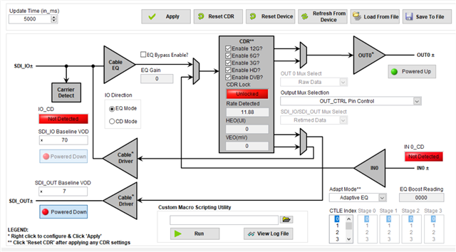
Recently we develop a optical fiber to 12G SDI converter using LMH1228.

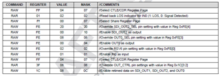
I wrote the code using the SNAU206.

This project use an optical fiber transceiver receive only.

When we inject the 12G SDI signal into the LMH1228 input, the same signal is not retransmitted to the outputs, however when we inject a signal lower than 12G the chip works normally.

What could I be doing wrong if I followed the programming instructions and commands contained in the Programming Guide?

Thanks

  • Hi Marcelo,

    1). Are you using I2C interface to set different register settings? If yes, please use USB2ANY so we can use GUI to control and monitor the part.

    2). Do you see Lock_N getting asserted?

    Regards, Nasser

  • Hi Nasser,

    I'll answer your questions below.

    1) No, I'm using a SPI interface to program the LMH1228. I'm developing this project in Linux Ubuntu 22.04 LTS.

    2) The LOCK_N getting asserted as soon as the board is powered up, even before connecting the SDI cable.

    Regards, Marcelo

  • Hi Marcelo,

    Got it.

    At 12G it seems we are getting locked to the 100-ohm signals on LMH1228 input. Please read:

    1). Please read CDR lock status(CTLE/CDR reg 0x02) multiple times to make sure we are not going in and out of lock.

    2). Afterward, CDR register 0x27 and 0x28 multiple times and check HEO/VEO eye opening.

    Regards, Nasser

  • Hello Nasser

    You mean I need to configure the LMH1228 to use the HEO/VEO settings, is that it?

  • Hi Marcelo,

    Please first check CDR to make sure we are locked reliably(note item #1 above). Then refer to the programming guide so you can read HEO/VEO values.

    Regards, Nasser

  • Hi Nasser

    I made a mistake when I said that the LOCK_N led is constantly lit, I was actually confused with another project we are developing with the LMH1218. In this case, the LOCK_N led is off when the board is energized and only lights up when there is an SDI signal at the IN0 input of the LMH1228.

    I wrote some commands referring to what you informed me in previous messages but even so the 4K signal is still not being recognized by the LMH1228, but when we inject a 3G SDI signal for example the chip works normally.

    Regarding the commands I mentioned above, the ones I tested in my code were:
    a) 0x11 0x00 0x20 -> Enable EOM pg.13
    b) 0x24 0x80 0x80 -> Initialize fast EOM pg. 13
    c) 0x3E 0x80 0x80 -> Enable Autoimatic HEO/VEO pg.14

    Well, if your intention in the previous messages was to make me insert these codes into my programming, that was done but I didn't get any positive results.
    But if your intention was to make me write all the commands from the tables from which I took the ones I mentioned above, that hasn't been done yet. Should I do the programming according to the tables on the pages mentioned above?

    I ask the question because the main programming consists of leaving the LMH1228 working to receive all the standards for which it was designed and in a way this happens except with 4K.

    I hope I have been able to provide a more general overview of how the project is going, if necessary I can post the part of the source code that is used to program the LMH1228.

    Regards, Marcelo

  • Hi Marcelo,

    Device should be able to lock even in pin mode. So you do not need to do any programming. Suggestions:

    1). In pin mode, please put scope on LOCK_N and check. If you see it toggling, you can also check HOST EQ settings on the device to make sure there is not over-equalization. Alternatively you can reduce signal level or disable de-emphasis on your FPGA or ASIC transmitter.

    2). Please try to get one of the LMH1297 EVMs so through the GUI you can control and monitor device status.

    3). If possible it would be a good idea to have SDI video analyzer like Phabrix QXS so you can monitor SDI signals.

    Regards, Naser

  • Hi Nasser

    Regarding the hardware configuration around the LMH1228, I followed the tables in the datasheet so that the component could function as simply and as normally as possible.
    I want to say that HOST_EQ is in float because according to the datasheet, normal operation is enabled in this configuration, Table 4.
    The OUT0_SEL pin is connected to GND by a 1k resistor, Table 2.
    The MODE_SEL pin is floated, Table 9, to enable SPI communication.
    The SDI_OUT2_SEL pin is also connected to GND via a 1k resistor, Table 2.
    The Enable pin is connected to the power supply via a 1k resistor, according to the table on page 3, Pin Functions.
    The OUT_CTRL pin is floated to enable the reclocker, Table 6.
    The SDI_VOD pin is on float to enable 800mVp-p, Table 7.
    These are the hardware configurations I applied to the LMH1228.

    I would like to better understand what you meant in item 2 of the last message you sent me.
    Regarding item 3, unfortunately we do not have this equipment.

    Regarding the programming of the LMH1228, I am following part of the content of the table contained in section 3.1.1 of the Programming Guide (SNAU206). I say that I'm following it partly because I realize that some commands don't make sense for what I intend to do. In addition to these commands, I use the commands from other tables that I will mention below:
    Section 3.1.1
    0xFF 0x04 0x07 -> Select CTLE/CDR page
    0xFf 0x00 0x07 -> Select Share Register Page
    0xFE 0x00 0x10 -> Enable SDI_OUT2 as output
    0xFE 0x00 0x04 -> Enable OUT0 as output
    0xFE 0x01 0x01 -> Enable IN0 as input
    0x1C 0x08 0x0C -> Enable retimed data on SDI_OUT1, SDI_OUT2 and
                                        OUT0
    Section 3.3
    0x15 0x00 0x40 -> IN0 Signal Normal Detection

    Basically this is the programming I did for the LMH1228, if you notice something missing or something extra, please let me know so I can correct it.

    Regards, Marcelo

  • Hi Marcelo,

    I think you may have missed some programming steps. Here is section 3.1.1:

    Please follow the exact steps. I think you are missing override bits.

    Regards, Nasser

  • Hi Nasser

    I wrote a routine based only on table 3.1.1 in the programming guide and the LMH1228 did not transmit in 4K.
    In conjunction with this action, we assembled a board of the same model that is using the LMH1228, but we did not do any programming, and only with the hardware configurations that I described to you previously, this board also did not transmit in 4K.
    Therefore, a question arises: what else do I need to do so that we can use our card to transmit 12G (4K) SDI?

    I was noticing in the datasheet that the RSV6 pin has a pull-up resistor connected to it.
    In our prototype this pin is floating, that is, without any connection. Therefore, what is the relevance of this pin so that our project can work correctly, transmitting in 4K and standards below this? Would you be able to inform me?

    Regards, Marcelo

  • Hi Marcelo,

    As noted in the data sheet, we must pull this pin to VIN to enable cable driver or LMH1228 mode. Please let us know the result.

    Regards, Nasser

  • Hi Nasser

    I will connect this pin and report back the result.

    Regards, Marcelo

  • Hi Nasser

    I put the pin in the VIN and I didn't have any satisfactory results, that is, the 4K still doesn't work.
    At 1080p it works normally, but when we inject a 2160p signal it doesn't work.
    I did the programming only using the table in section 3.1.1 of the programming guide and there was no satisfactory result.
    I tested other programming codes in order to disable some functions that could perhaps be enabled, but we also did not have satisfactory results.
    I used a new board that does not have any programming, on this board I also connected pin 5 to VIN using a 1K resistor, as instructed in the datasheet, and the results were the same, in 4K it does not work.
    We need an urgent solution so that our equipment can work as we are wasting time and resources.

    Regards, Marcelo

  • Hi Marcelo,

    Nasser is out of office this week.  We will review and get back to you with some recommendations tomorrow.  Thanks for your patience.

    Thanks,

    Drew

  • Hi Marcelo,

    Since Nasser is out of office I will support in the meantime.

    As Nasser mentioned earlier, what might help your design is using the LMH1297 EVM. With the LMH1297 EVM GUI, you would be able to program and see the status of the registers in a visual form. Here's an example:

    Is that something that would interest you?

    If not, I suggest looking at some of Nasser's other responses. For example, this comment could be useful:

    In pin mode, please put scope on LOCK_N and check. If you see it toggling, you can also check HOST EQ settings on the device to make sure there is not over-equalization. Alternatively you can reduce signal level or disable de-emphasis on your FPGA or ASIC transmitter.

    Best regards,

    Nick E.