Other Parts Discussed in Thread: TCA9802, TCA9517, PCA9306, TCA39306, TCA9517A
Hi,
Want to simulate the I2C lines. How could I find/get the IBIS model for the I2C drivers?
Thanks.
BR
Li
This thread has been locked.
If you have a related question, please click the "Ask a related question" button in the top right corner. The newly created question will be automatically linked to this question.
Hi Li,
We currently do not have an IBIS model for the TCA9803.
We do have an IBIS model for the TCA9802.
https://www.ti.com/product/TCA9802#design-tools-simulation
The TCA9802 can be used to simulate similar to the TCA9803. The only difference between TCA9802 and TCA9803 is the ICS strength.
Regards,
Tyler
Hi again,
I can see that the SCL/SDA_A is much stronger and faster than the B-side, I wonder if you have similar I2C level translator product (both side 3V3) but with weaker A-side? Thanks.
Hi Li,
The expert supporting this case is currently out- I will try my best to fill in for the time being.
By "weaker" did you mean a higher VOL is desired, except on A-side? Since VCCA = VCCB, are you able to swap A and B side to match the desired VOL?
You can also see the TCA9517/TCA9617 that has a heightened VOL on B-side and configure it on your A side instead.
Regards,
Jack
Hi Li,
Are you talking about driving a logic low signal or logic high signal? I expect releasing to a logic high using this IBIS model will show up differently on the B-side vs. A-side due to the internal current source strength present on the B-side.
Also the TCA9802 is an I2C buffer. If a level translator is desired, then I suggest using the PCA9306 or TCA39306. Both products also have IBIS models on the product page on ti.com.
Regards,
Tyler
Thanks for the reply. For this application, a buffer is good enough since we do have the same 3V3 on both sides, just belong to different power domain.
I'm talking about the logic low signal. With the SDAA pulling low, the equivlent output impedance is quite small and the fall edge is pretty fast which causes some issues with our super long I2C channel. I wonder if any similar device with much weaker driver so longer falling time. Thanks.
Hi Li,
The TCA980x can be used for applications where VCCA can be greater, less, or equal to VCCB.
Is this short fall time observed in the IBIS model or during testing with real silicon? If IBIS model, are there any external loads configured on the outputs to replicate your system setup? If evaluating with real silicon, what device is driving the logic low? Is it possible to configure the drive strength, or add a series resistor/ small capacitance to the signal line to increase the fall time?
Regards,
Jack
We currently see the issue within simulation while using IBIS model. Our application has a very long I2C channel, with the total electrical length of around 11ns, therefore comparing to the typ 9ns falling time of this device, the channel is not lumped length any more which would create an overshoot at the receiver end. In simulation, we need to add a Rserial to dump that. If to add a Cshunt, it could also work but with a large cap value, and considering the other devices on the line, that will make the risetime too slow to meet the standard requirement.
I'm thinking if there is a footprint compatible device as TCA980x but with weaker driver with falling time much longer like 40ns or so, so that our long channel could be treated as lumped length, then we could be benefit from it.
Hi Li,
It looks like TCA9517A could be an option then.

The transition times seem to show output fall times >40ns. I would suggest in simulation however that the TCA9517A's A-side be connected to the long cable length if possible. Connecting the SVO side (B-side) to the long cable length could result in excess ringing due to larger amounts of inductance on the B-side.
TCA9517A also has an IBIS model in the product portfolio and is p2p to the TCA980x. TCA9517A does not have low VOLB however (~0.52V).
Regards,
Tyler
Thanks for the recommendation. The proposed part looks promising. However, there are some additional issue that I want to double check regarding the IBIS model. It's very simple setup as shown below, and the TRL is 1ns, Pull up Res is 2k, and Cshunt is set to be open, all drivers are set with 3V3 for TCA9517, and 3V6 for 9802.
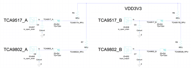
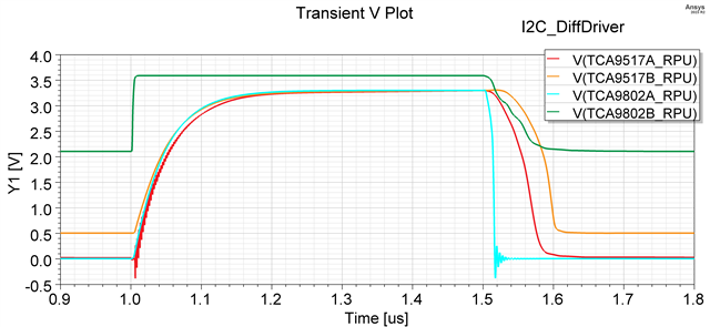
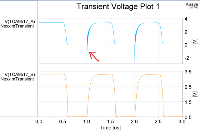
The following is the result plot. The questions are:
1. VOL level for 9802_B is very high
2. The ringing shown at the rise edge for 9517_A.
Could you pls double check the IBIS model and confirm if it would be the true phenomenon or if it is simulation only.
Thanks a lot.
Hi Li,
Try removing the pull-up resistors on the B-side of the TCA9802. TCA9802 was never designed to have pull-up resistors implemented on the B-side due to the internal current source (ICS) in the design.
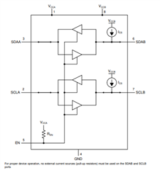
B-side is sensitive to external sources of current i.e. pull-up resistors, leaky esd cells, etc. The device conducts direction control via detecting whether current is being sinked inside the device, or current being sinked from the device externally.
Regards,
Tyler
Of course, that I have missed in my previous setup. However, in the simulation, even if I removed everything at the output, so it is purely TCA9802_B driver, the low level lowered a bit but is still close to 2V. Is there anything else that I missed in the setup?
BR
Li
Hi Li,
I am wondering if it is a model concern. Can you try setting the VCC of the TCA9802 to 3.6V instead of 3.3V?
Regards,
Tyler
Hi Tyler,
I also a bit suspect if it is the model. Now I've set it so that it has only the SDAB driver with no load, as shown below. I've set all 3 different voltage level options, and for each driver, it is powered internally and output only 1010.
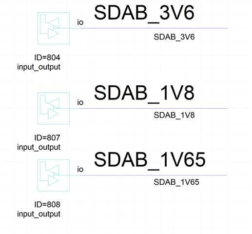
This is how the output curve looks like below, with VOL 0.38-2.07V. While in the datasheeet, it actuallys states typ VOL 0.22V and max 0.26V for TCA9802.
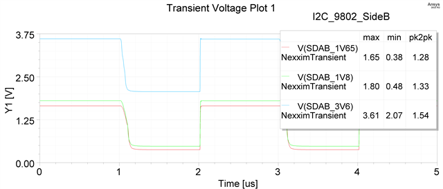
Li,
Yeah this looks like the model is off on the VOLB. Unfortunately our process to update this type of model is normally done by the design team in the past. Given that this is an older model (2017), it would take some time to redo this model and since most of our team is ooo until January 2nd due to holiday, work towards a new model would be further delayed.
How important is this model for sim? If we decide to proceed with the update of this model, I would need to consult my team to get an idea of how much work this would be. My suspicion is that is could be several weeks from today to produce an updated model.
Regards,
Tyler
Hi Tyler,
Thanks for the confirmation. I want to bring up another thing about the TCA9517 sideA model. Simple setup with 2k Pull Up resistor. Output 1010. Same setup for sideA and sideB model.
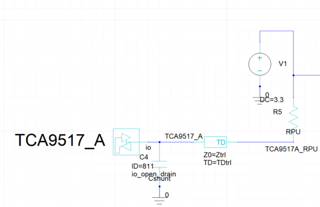
This is the output plot. As pointed, the rise edge shows ringing effect which should not exist for open drain buffer. Could you also check this? Thanks.
We want to finalize our design late January. It would be very helpful if we could get the updated model before that.
Again, thanks for quick response!
BR
Li
Hi Li,
It looks like our models are not functioning well, and the current resources that we have to devote to updating the models might take considerable time due to various circumstances like the holidays and recent team shift of the portfolio.
I wouldn't count on IBIS being updated for both devices by the end of January. What implications would this have on design? Can we move to different ways to qualify/validate the device?
Also, does adding any series resistance help to mitigate this spike? I agree, this behavior looks strange. Normally I would suspect this ringing to occur on a fast edge transition from high to low, not when the pull-up resistor is doing its job.
Regards,
Tyler
Ok, thanks for the inforamtion, so we know we should not wait for the simulation to qualify the device. We have been using this device before, so in normal user case it should be fine. However, I'd appreciate it very much if I could get updated once there are new version of the models.
Thanks again for all the discussion!
Hi,
Glad we could talk about this. I made a note in actions items for our I2C IBIS models for the team. I will talk with upper management and design teams to see what actions we can take to update the models.
Regards,
Tyler