This thread has been locked.

If you have a related question, please click the "Ask a related question" button in the top right corner. The newly created question will be automatically linked to this question.

PCF8574: PCF8574 and PCF8574A failing I2C ACK to TIVA Processor when bit 0 = 0

Part Number: PCF8574
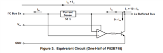
Other Parts Discussed in Thread: , TM4C129ENCPDT, P82B715

I am writing to PCF8574 and PCF8574A devices using the TI driver under TIRTOS.

TM4C129ENCPDT processor, latest TIRTOS available for this processor is being used.

The writes are always working, but the callback does not always return true.

If I write a 1 to bit 0 of the IO expanders, I always get true returned.

However, if I write a 0 to bit 0, some devices will always return with a FALSE state from the driver.

Some devices basically fail every time, others intermittent.

The write itself always works and the outputs are correctly activated but the ACK is not detected and hence the TI driver returns a non successful transfer.

As I wish to be able to detect when the chip is present this causes an issue as I cannot detect the difference between a missing chip or chip not responding because bit 0 is 0.

I noticed someone else reported a similar issue in stack overflow, but no solution was offered.

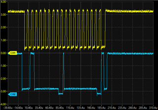
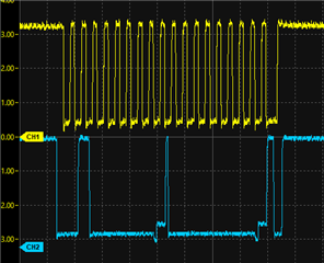
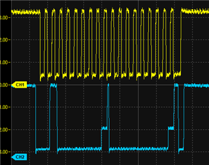
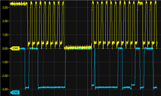
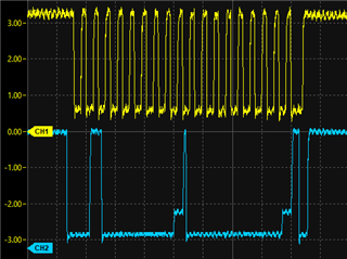
Looking on a CRO it looks like there is an ack but it is delayed sometimes when bit 0 is 0, it is very consistent when bit 0 is 1.

Is there any adjustment that can be made to the driver to allow for a longer delay for the ACK, or is this fixed in hardware.

Issue occurs at both 100kHz or 400kHz so is not speed of the I2C bus related.

  • Hi Barry,

    I am not familiar with our TI-RTOS MCU system, and the TI driver that comes with it. I am assuming if the driver came from TI, we would have tested the I2C drivers to be compatible with 100kHz and 400kHz I2C operation. 

    Since changing the speed doesn't affect the outcome (mostly rise-time), I would suspect that maybe it is a logic level issue, possibly the pull-ups are too strong? Do we have a schematic and scope captures that could help us analyze the I2C SDA & SCL waveforms of your design? 

    Do you by chance have the hyperlink to the stack overflow thread you were mentioning? Maybe I can take a look and get more background of what we are dealing with here. 

    Regards,

    Tyler

  • Hello Tyler

    The stack overflow post is:

    i2c - PCF8574 doesnot send ACK - Stack Overflow

    I use the exact same I2C hardware with same 2k7 pullups to interface to flash memory, one wire, mac address chip and STM32 processor acting as a slave.

    All of these work reliably all of the time and have done so for many years.

    I have used the PCF8574 previously in other designs, but these simply ignored any errors as the write were actually working, this application needs to be able to report a failure.

    I will try and get some CRO signals on Monday.

    I am thinking of just modifying the TI I2C driver so that I can flag if the device acks the address byte (This is always happening) and only reporting an error if the address isn't acked, rather than if the data byte isn't acked.

  • I forgot I had inverted set on my output write (one of our software configuration settings).

    The error occurs when bit 0 = 1, not bit 0 = 0

    I couldn't upload images, it said it didn't like the URL, so here are drop box links, which hopefully work for you.

    Here is the trace when bit 0 = 0 and the ACK works fine

    https://www.dropbox.com/scl/fi/qb8yw4flx42mxmb56cy28/I2C_bit0_ok.png?rlkey=vgukpenatg2yeb2zq0v88pjqi&dl=0

    However, when bit 0 = 1

    https://www.dropbox.com/scl/fi/fgz8dm26mefvek38wr3vl/I2C_bit0_err.png?rlkey=g2dcooyy6cfgkvx97wan5igrc&dl=0

    I always get failed from the I2C driver

  • Hello

    I have done some further checking and find the issue seems to be related to the P82B715 line extender.

    The PCF8574 buffers are after a pair of 82B715.

    Path is Processor to 82B715, short cable to another 82B715 then the PCF8574.

    The traces I captured were from the PCF8574 side and look fine.

    However, when I look at the "S" side on the processor, the ACK signal does not pull very low at all, being around 1.4V.

    Supply to all devices is 3.3V, the Pullup on "S" side at processor is 1K, Pullup on "L" side is 270R and pullup at the PCF8574 is 4k7.

    I worked out that simple paste works for the images, rather than the insert image button.

    Here is signal at the PCF8574

    Then signal on the line between the two 82B715 (L signal on each)

    And finally, the S output of the 82B715

    You can see the ACK signal is not going anywhere near the ground.

    I will check further then update, changing the CPU pullup to 10k made no difference.

  • I changed the line Pullup from 270R to 1K and this works better, however there is an obvious difference between another peripheral device on the I2C, in this case an STM32 processor.

    Here you can see the ACK is much lower at the CPU end.

    VS the PCF8574

    Where you can see the ACK is much higher at the CPU end.

    So, I now have it working, but need to use different resistor values for the PCF8574 vs the other devices.

  • The I²C specification requires that the pull-up current on SDA is at most 3 mA. In this case, the PCF8574 is guaranteed to pull the line lower than 0.4 V.

    So with a 3.3 V supply, the effective pull-up resistance must be at least 1.1 kΩ. Are there multiple pull-up resistors in parallel?

  • Thanks for the answer. 

    Yes there are resistors in parallel and the parallel impedance is 175R for 18mA total sink.

    However, the role of the 82B715 is to extend the capability of I2C to allow longer line lengths and it does this by increasing the current which can be driven from 3mA to 30mA on the line side (multiply by 10). 

    From the datasheet: 

    Drives 10× Lower-Impedance Bus Wiring for Improved Noise Immunity

    The P82B715 is a device for buffering highly capacitive I 2C bus systems, and it supports bidirectional data transfer through the I 2C bus. The P82B715 buffers both the serial data (SDA) and serial clock (SCL) signals on the I 2C bus and allows for extension of the I 2C bus, while retaining all the operating modes and features of the I 2C system.

    I would expect that this should be a linear relationship to the sink on the device side, rather than imposing the same 30mA requirement on the device side.

    For 3.3V operation, the datasheet quotes 2.6mA on the device side and 24mA sink Current, so there shouldn't be an issue with the resistors being used.  For this particular operation, I don't need the full 24mA, so can change the resistors.  The Datasheet also says that 30mA line should give 3mA device side pull down and 3mA on the device side should result in 30mA on the line side.  

  • Sorry, I forgot about the extenders.

    When the PCF pulls low, it sinks all current through its own pull-up, and one tenth of the current through the other pull-ups. So it sees 3.3 V / 4.7 kΩ + 3.3 V / (10 × 270 Ω) + 3.3 V / (10 × 1 kΩ) = 2.25 mA. This should be OK.

    The PCF outputs at most 0.4 V, but each P82B715 adds the voltage drop of the 30 Ω resistor. Are there any other series resistors or switches/muxes on the I²C line?

  • Thanks for that, the 30R explains the raised level, there is a 100R series resistor as part of protection circuitry.