Part Number: DS90UB940N-Q1
Hi Team,
Tier1:Neusoft
OEM: Geely
We found that there are differences in the power-on timing of 940 and 940N. What is the reason for the change?
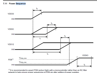
940:
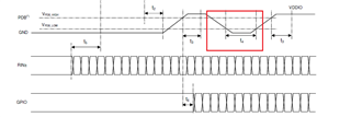
940N:
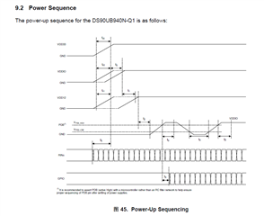
What is the second PDB pull-up of 940N? Why was this change made?
Because the customer may have no waveform output in the 940 mipi csi data lane (2 data lanes are used), which will lead to no image problem. After inspection, it was found that they were using 940N, but the timing was done with reference to 940, and then after changing to the power-on timing required by 940N, the problem disappeared. Customers want to know what the root cause is?