- Ask a related questionWhat is a related question?A related question is a question created from another question. When the related question is created, it will be automatically linked to the original question.
This thread has been locked.
If you have a related question, please click the "Ask a related question" button in the top right corner. The newly created question will be automatically linked to this question.
In this E2E FAQ, I am going to provide an overview of RX detect with specific information on the RX detect pulse width and frequency, then, I am going to discuss hot plug functionality for Gen 5 redrivers with specific information on the register sequence for an RX detect reset on a per channel basis.
The Receiver Detection circuit is implemented as part of a Transmitter and must correctly detect whether a load impedance equivalent to a DC impedance of 40 Ω-60 Ω is present. It is required that the detect sequence be performed on both conductors of a differential pair.
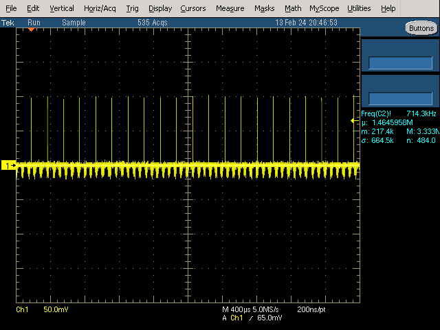
Receiver Detection on the positive conductor of channel 1 on the DS320PR810 is shown below:

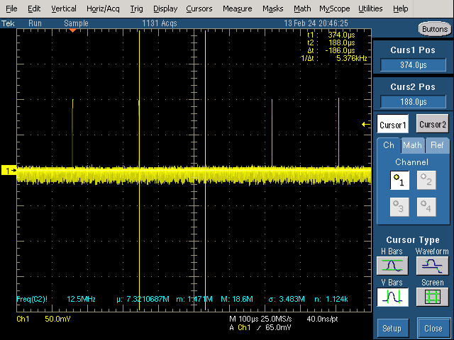
The pulse frequency is ~5.4KHz:

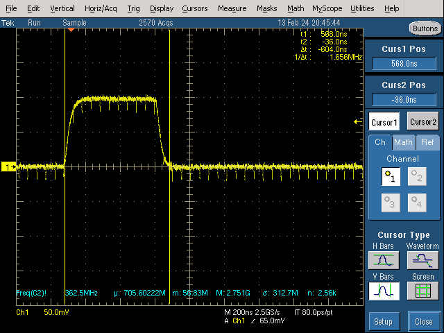
The Pulse Width is ~568ns

TI PCie redrivers will be able to pass the packets associated with a hot plug event dictated by the PCIe Base specification. Occasionally, it can be beneficial to manually reset the Receiver Detection process in the redriver by using register writes. The benefit of going through the register sequence to reset the device's Receiver detection process is the flexibility to control the Receiver detection on a per channel basis. This flexibility is essential for low channel count endpoints and applications where multiple endpoints are connected to one redriver.
For the Gen 5 devices, the register corresponding with output channels is in each row of the table below:
| Channel # | Register |
| 0 | 0x0A |
| 1 | 0x2A |
| 2 | 0x4A |
| 3 | 0x6A |
The command sequence for one Receiver detection reset is:
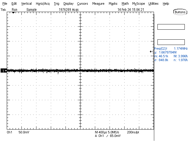
The waveform displayed on the scope when the RX detection address is set to 0x05 is below:

Best Regards,
Nick