This thread has been locked.
If you have a related question, please click the "Ask a related question" button in the top right corner. The newly created question will be automatically linked to this question.
Hi TI experts,
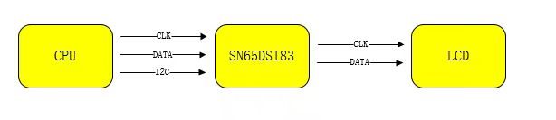
We want to use SN65DSI83 between CPU and LCD display as below:
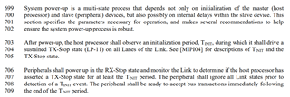
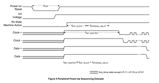
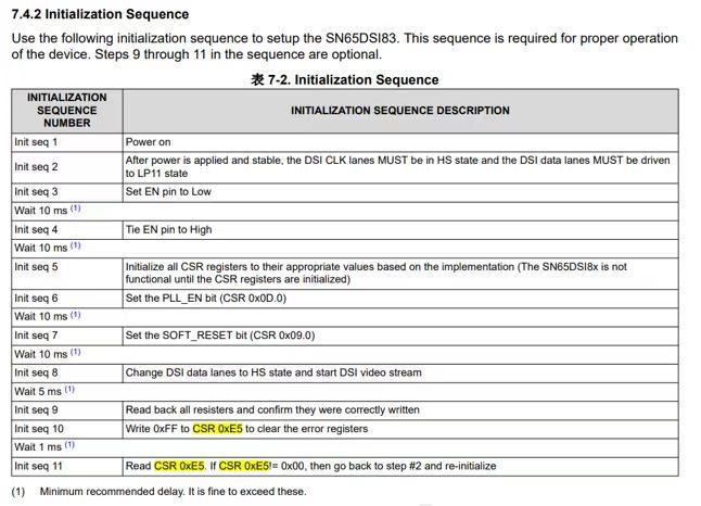
Now we configured according to the steps in the data sheet, but in the second step, the DSI data must be driven to LP11 state (that is, setting the data to high level) was limited by the underlying driver of the CPU. We could only let The data is kept output, and then the following series of resets, register configuration, PLL enable and other operations are performed. But in the end, the internal PLL of SN65DSI83 could not be locked.
if there is a way to solve this situation.
Hey Gary,
Unfortunately you will need to find a way to fix the drivers of the CPU, as the LP11 state upon startup is a requirement per the MIPI spec:
You can additionally test the functionality of your system on the TX side of the DSI83 by enabling the color bar (table 7-8 in datasheet)
Hi VP,
Now SN65DSI83 can work well and can normally output signals.
Another question is that all the NC pins from SN65DSI83 can be uesed for pin out and they don't connect anything eles inside the SN65DSI83.
Hey Gary,
What do you mean by "used for pinout"? These pins should not be connected and should be left as floating.
Best,
Vishesh Pithadiya
For PCB routing. For example, a certain signal line is drilled on a certain NC pad and passed to other PCB layers.
Hey Gary,
I would not recommend doing this as you do not want any signal connected to any of the RSVD pins even if the signal is not high speed.