This thread has been locked.

If you have a related question, please click the "Ask a related question" button in the top right corner. The newly created question will be automatically linked to this question.

TIC12400: Switch State Change (SSC) Interrupt generated

Part Number: TIC12400

Hi,

I configured the TIC12400 but eventhough the level on the INx is changed from 11V to 0V (switch to GND), there is NO SSC interrupt generated.

When switch x switches to GND, the current will go up x * the wetting current

INx all configured as CSO

WC_CFG0,WC_CFG1 2mA or 10mA (only above current will increase)

IN_EN all enabled

INT_EN_COMP1, INT_EN_COMP2 all set to 3 (falling and rising edge)

INT_EN_CFG0 All interrupts are enabled

CONFIG = 0x7E18E8 (continous mode)

Mode  all zero.

POR, CALC_CRC, UV  interrupt can be received when doing SW reset / init / low voltage

Any idea why it doesn't work?

Thanks,

Paul
  • Hi Paul,

    Are you using comparator or ADC? If you are using the ADC ensure that INT_EN_CFG1 to INT_EN_CFG4 are configured correctly.

    How are you configuring the threshold values for the input you are testing? 

    Regards, Amy

  • Hi Amy,

    I use comparator mode, and have set threshold to 2.7V

    All other threshold are not defined (zero), Need to set when using comparator mode?

    Thanks,

    Paul

  • Hi Paul,

    If you have selected the 2.7V threshold that should be ok. In continuous mode, an interrupt is always generated after the 1st detection cycle (after the TRIGGER bit in register CONFIG is set to logic 1). Are you able to detect this interrupt? 

    (then, in subsequent detection cycles, the interrupt is generated only if switch status change is detected.)

    Regards, Amy

  • Hi Amy,

    I use polling by reading INT_STAT register every 5 mSec, when do SW reset, I get POR

    if doing CALC_CRC I get CALC_CRC 

    But I get never SSC flag set in the INT_STAT, not the first time and also not when changing switch status

    I have measured the input voltage at INx and is 11 V when switch is open and almost zero when closed.

    Regards,

    Paul

  • Hi Paul,

    I just realized that you didn't mention setting the SS_EN bit. This is likely your issue - ensure this bit is set to 1. 

    Regards, Amy

  • Hi Amy,

    INT_EN_CFG0 All interrupts are enabled. 

    Paul

  • Hi Paul,

    Please try reading register 0x01. You should see the device ID value of 0x20.

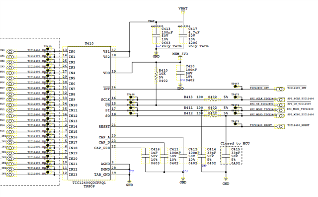
    Additionally, the INT pin is an open drain output that requires a pull-up resistor. Your schematic does not include this, but since it is only a schematic snip-it, ensure that you have included either an external pull-up, or check if the MC has an internal pull-up.

    Finally, please load the register writes here and I can check the configuration on a TI EVM.

    Please refer to this application note as a supplemental resource: Steps to Configure TIC12400-Q1 Multiple Switch Detection Interface (MSDI)

    Regards, Amy

  • Hi Amy,

    I have read register 0x01 and has value 0x20.

    Also read register 0x03 and have the value 0xFFFF at power ON.

    So SPI has correct functionality.

    The INT PIN has external pull-up.

    Anyway I am currently using pulling by reading INT_STAT every 5 mSec.

    setting as below:
    CONFIG         0xFE18E8           Continuos mode
    IN_EN             0xFFFFFF      All inputs enabled
    CS_SELECT    0x000000        All CSO Switch to GND
    WC_CFG0      0x492492       Wetting current 2 or 10 mA
    WC_CFG1      0x092492
    THRES_COMP    0x000555      2.7 V threshold
    INT_EN_COMP1 0xFFFFFF      Enable all interrupts Falling and raising edge
    INT_EN_COMP2 0xFFFFFF
    INT_EN_CFG0   0x000FFF        All interrupts enabled     
    Mode             0x000000      Comp. mode
    Paul
  • Hi Amy,

    Any progress of this problem?

    Thanks,

    Paul

  • Hi Paul,

    Thank you for sending along your register writes. Would it be possible to provide the entire register map and the order in which you are configuring?

    It appears that sequence in which the Trigger bit is set matters. The Trigger bit is part of the CONFIG register and must always be set to '0' before other registers can be written to. You should always write to the CONFIG register first to set the Trigger bit to '0'. Referring to section 5.3 in the Steps to Configure TIC12400-Q1 Multiple Switch Detection Interface (MSDI) document, the trigger bit should not be set until step 6, "Start TIC12400-Q1 operation by setting the TRIGGER bit in CONFIG register to 1 and read the INT_STAT register to clear the baseline SSC interrupt (Step 6)."

    Regards, Amy

  • Hi Amy,

    All register settings written also in this order! Is the order of writting important? except TRIGGER Bit of course

    0x1A -> 0xFE10E8 (TRIGGER = 0)

    0x1B -> 0xFFFFFF

    0x1C -> 0x000000

    0x1D -> 0x492492       

    0x1E -> 0x092492

    0x1F -> 0x0

    0x20 -> 0x0

    0x21 -> 0x000555

    0x22 -> 0xFFFFFF

    0x23 -> 0xFFFFFF

    0x24 -> 0x000FFF

    0x25 -> 0xFFFFFF

    0x26 -> 0x333333

    0x27 -> 0x0C30C3

    0x28 -> 0x0000C3

    0x29 -> 0x0

    All zero

    0x32 -> 0x0

    0x1A -> 0xFE18E8 (TRIGGER = 1)

    Start measurement (registers frozen)

    0x1A -> 0xFE1AE8 (CRC_T = 1)

    Received CRC same as Calculated CRC

    Paul

  • Hi Paul,

    Thank you for providing this. I do not see any issues with these register writes for the configuration you have described. Let me test this sequence and full register map you have provided here on a TI EVM tomorrow and I will get back to you.

    Thanks again, Amy 

  • Hi Paul,

    I setup the TI EVM to test these register writes, and saw the same behavior that you have described.

    I configured the device using the GUI in the modes you have mentioned, and saw the interrupt correctly work. After comparing the register writes I believe that your issue may be coming from the setting in the CONFIG register (0x1A). There is a conflict setting WET_D_INx_EN bits while using the comparator feature. Try setting these bits to 0. Additionally, if you are not using the INT_CONFIG with the dynamic try setting this to static.

    Please reach out if you have any other questions.

    Regards, Amy

  • Thank you Amy.

    When disable WET_D_INx_EN bits, I get the CCS interrupt when TRIGGER, and also when switch status is changing.

    I checked the datasheet and it don't say anything anbout this issue, it should be able to preform during normal operation.

    Anyway now it works like expected!

    Thanks,

    Paul

  • Hi Paul,

    Yes, I agree the datasheet is not super clear on this - it only mentions that "it is critical to configure the current source/sink appropriately and program the input to ADC input mode before activating the wetting current diagnostic feature to prevent false interrupts from being generated.". 

    Thank you for the feedback on our datasheet and glad to hear that things are working for your configuration. Please reach out for any other questions.

    Regards, Amy