This thread has been locked.

If you have a related question, please click the "Ask a related question" button in the top right corner. The newly created question will be automatically linked to this question.

SN65HVD1473: RS-485 tranceiver schematic (SN65HVD1473)

Part Number: SN65HVD1473

Hello, I'm not very familiar with RS-485 communication, and I'm currently working on a project where I need to implement it to communicate with different MCUs. I'm using the SN65HVD1473 as an RS-485 transceiver. I came across the schematic of the RS-485 Full Duplex evaluation module. I want to know what's the utility of resistors R12, R13, and the capacitor C10 marked in the red rectangle, and should I also include them in my design with the SN65HVD1473? Additionally, should they be placed only between the Z and Y pins or also between A and B?

Thank you for you help!
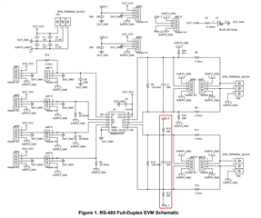
  • The EVM has many testing/debugging options that you do not actually need.

    R12/R13 allow you to pull the bus lines to some voltages called "VCM_Z"/"VCM_Y". This is usually not needed for the SN65HVD1473, but if you have some receiver without fail-safe inputs on the bus, then it might be useful to have one set of fail-safe resistors somewhere on the bus.

    C10 appears to be a low-pass filter. You should not try to slow down 20 Mbps signals.

  • What do you mean by fail-safe inputs on the bus ? Can you please explain ?

  • When the bus is shorted (by the termination resistor when idle), the differential input voltage is zero. In this case, the THVD1473's receiver is guaranteed to output a high signal.

    There are receivers that do not handle a voltage of zero correctly. For them, you should add pull-up/-down resistors somewhere on the bus.

  • Hi Ali,

    What Clemens has indicated for the R12/R13 resistors is correct.

    The C10 capacitor is used as a low pass filter - but mainly used to help attenuate higher frequency noise. Some designers do like adding these to help with higher frequency noise - but they are not necessary and usually aren't included in most designs. Generally we see like 50pF to 100pF when they are used. These capacitors can reduce the effective max length of the bus as well. 

    Clemens is also correct on idle fail-safe - we do have an application note that goes into greater detail on how to size these resistors: https://www.ti.com/lit/an/slyt324/slyt324.pdf

    These "fail-safe" resistors can also increase the noise margin for devices with Idle fail-safe. 

    Please let me know if you have any other questions!

    Best,

    Parker Dodson

  • Thank you for response! 

    Does the SN65HVD1473 transceiver include the Idle fail-safe ?

  • Hi Ali,

    Yes this device is open/idle/short fail-safe. 

    Above is a section of the datasheet. You can tell if a device is open/idle/short fail-safe if all of the VIT+ (some datasheets will call it VTH+) specs are < 0V - since the max value of VIT+ is -20mV that means when the bus is idle, open circuited, or short circuited the output at the "R" pin will read high. When the bus is idle/shorted/opened the input differential voltage should be about 0V.  

    Best,

    Parker Dodson

  • Thank you for your response!

  • Hi Ali,

    No Problem - if you have any other questions please don't hesitate to reach out!

    Best,

    Parker Dodson