Other Parts Discussed in Thread: TUSB211
Dear TI Engineer,
We have some question about the application of TUSB211A, the details are as below:
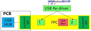
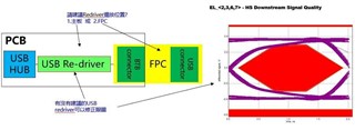
1) Because our eye diagram test failed (Host mode), so I would like to ask if TUSB211AI can correct the eye diagram? Or is there any other p/n for recommendation? Our architecture is as follows: the motherboard is connected to the USB connector through an FPC, and we plan to place the re-driver on the FPC near the USB connector end.
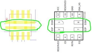
2) TUSB211AI has D1P/N and P2P/N. We would like to confirm which end is connected to the CPU (HOST) end and which end is connected to the connector (device) end.
Due to the two of the three explanatory diagrams on the datasheet have the same connection, but one has a different connection. The three connection diagrams are as follows:
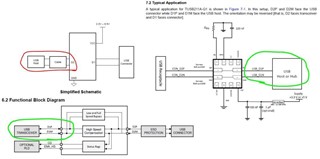
3) The following is the suggested footprint on the spec. We need to confirm whether the footprint D1P should be directly connected to D2P and D1M should be directly connected to D2M. Is this correct?
Thanks,
Kind Regards