TCAN1146-Q1: RXD pull high during mode transition

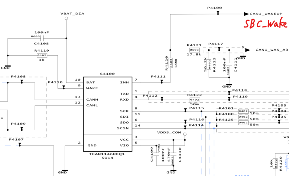
Part Number: TCAN1146-Q1

Tool/software:

Hi team,

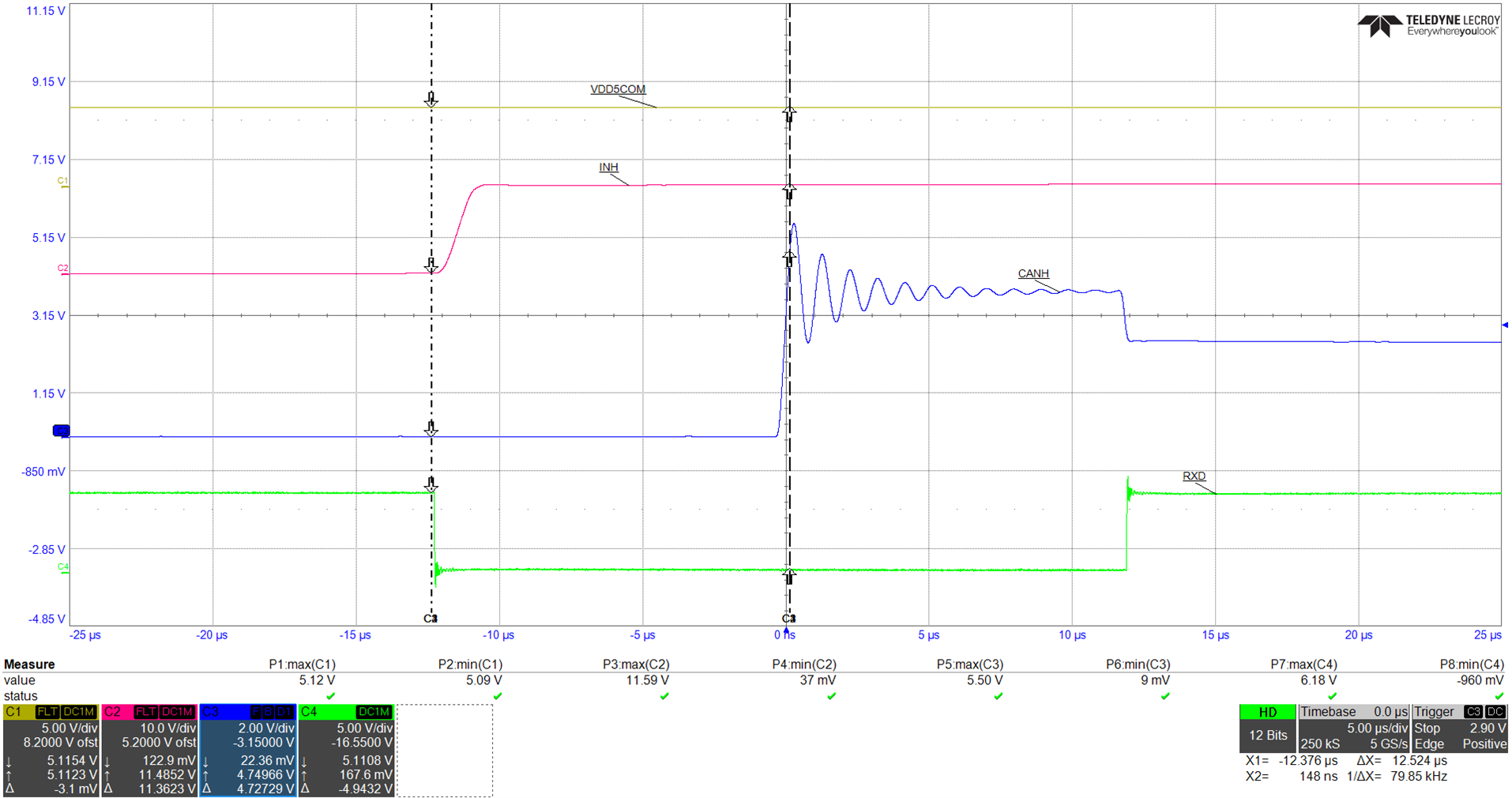
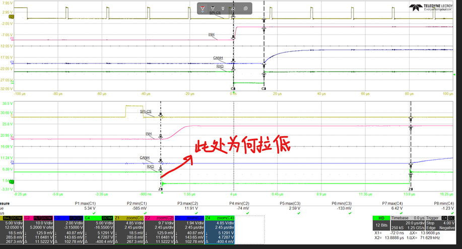
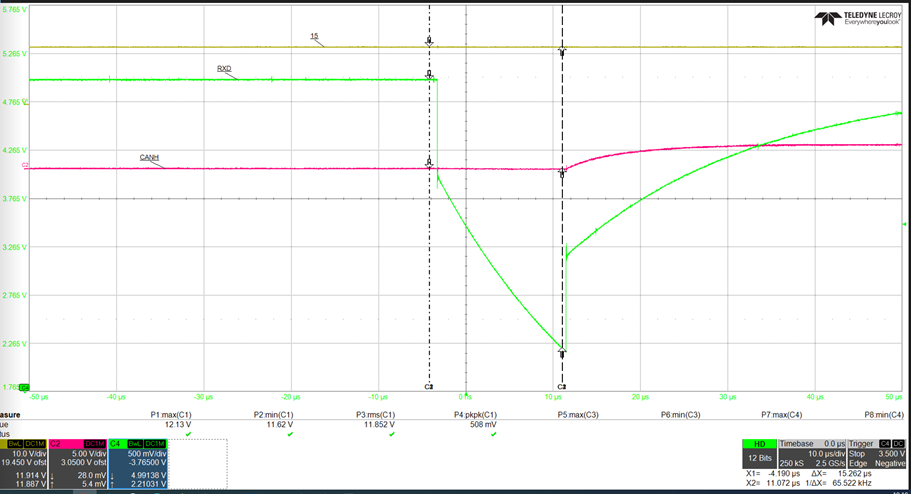
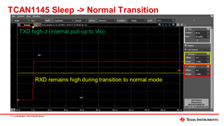
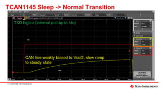
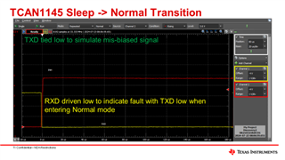
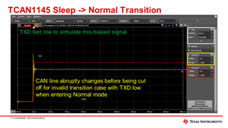
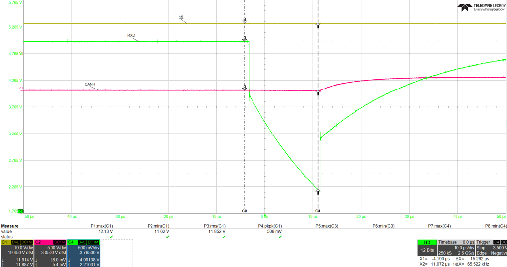
Customer is using TCAN1146 in their design, and use SPI to configure device status change from sleep mode to normal mode. They found RXD will be pull low as below. Would you please help share your comments why this happens?

Thanks

Scarlett

  • Hi Scarlett,

    It looks like the RXD pin may be unpowerd for a moment here during this test. The RC decay after the initial edge would indicate that the internal (or external?) pull-up is disabled or unpowered. Similarly the rise-time for this signal is very slow, which seems to me more like a power supply coming up than a digital signal driving high. Do you know what the state of the Vio supply is during this test? Is this supply dependant on the INH signal state (used as EN signal for voltage regulator)?

    Is another oscilloscope channel available to monitor the nCS and INH signal as well? I would be curious to see how this RXD behavior lines up this SPI communication and the INH signal indicating when the device is in sleep mode. 

    Regards, 
    Eric Schott

  • Hi Eric,

    Please see attach below

    Figure1 is take when RXD and MCU are connected. VDD5COM is VCC and VIO power supply. You could see VDD5COM is always stable and no power loss.  Figure2 is taken when RXD and MCU disconnected, RXD will be pull low 14us, could you explain why happens?

    Thanks

    Scarlett

  • Hi Scarlett,

    At the marked time it looks like the TCAN1145 is responding to a wake event. Any such wake from sleep would cause the INH pin to assert high and the RXD pin to drive low to indicate the to MCU that there is a pending wake request. Because we can see that the CAN bus in idle at this time we can assume this was either a local wake up (LWU) from the WAKE pin or the MCU has requested a mode change via SPI - the second seeming more likely here given the activity on nCS. Because a mode change from sleep to any active mode can take some time (tINH_SLP_STBY = 100us max) this wake could be in response to one of the earlier SPI frames we can see from this scope shot. 

    The rising edge of RXD is likely the point where a SPI command moves the transceiver into normal mode, disabling the wake indication on RXD and activating the CAN driver and receiver. This aligns with the CAN bus bias becoming active as we see CANH start to rise to the desired common mode voltage of 2.5V. 

    All of this behavior looks expected based on the typical use of the TCAN1145 and the surrounding signals. Is the customer experiencing some issue with this behavior on a system level or are they only curious about what they have observed here? 

    Regards, 
    Eric Schott

  • Hi Eric, 

    Thanks for your reply. Customer is sending command through SPI to change from sleep to normal. TRX pull low RXD will cause MCU receive the wrong info and sending wrong frame to the bus. They have tested TJA1145 as well but seems only TI TCAN1146 have this issue. They have test two pcs, the phenomenon are a little bit different. Pls see below and pay special attend to the pointed moment. Thanks

    Scarlett

  • Hi Scarlett,

    Please give me another day to look at this. I will have a reply for you by Monday morning Dallas time. 

    Regards,
    Eric Schott

  • Hi Eric

    Could you please help share your feedback?

    Thanks

    Scarlett

  • Hi Scarlett,

    Are the two waveforms here from the different PCBs that were tested? Or are both of these behaviors shown on but PCBs? 

    When the transceiver wakes into normal mode, what is the status of the device interrupt registers (50h - 53h)? I would like the see if the device is registering any wake events besides the SPI command from the MCU. 

    The slope of the RXD pin in the last scope shot is not typical for the general use case of this pin. I believe there is some power component that is complicating the behavior here. Can you please share a schematic of the customer system that shows how Vcc and Vio are sourced and other IC dependencies on the INH signal? 

    Regards, 
    Eric Schott

  • Hi Eric,

    Are the two waveforms here from the different PCBs that were tested? Or are both of these behaviors shown on but PCBs? 

    Yes they are different PCB, all use TCAN1146 and same software

    When the transceiver wakes into normal mode, what is the status of the device interrupt registers (50h - 53h)?

    50h:C0C0

    51h:C006

    52h:C000

    53h:C000

    Schematic pls see below

    TThanks

    Scarlett

  • Scarlett,

    The interrupt register information you shared shows that the CANSLNT, and CANTO flags are set, which means the CAN bus was inactive for tsilence. Can the customer confirm the mode of the device before and after the SPI command to go to normal mode is sent? The behavior looks similar to if the device were going into Standby mode rather than Normal mode.

    Also, I believe this was already answered, but there is no external pull-up on RXD, correct?

    Regards,

    Eric Hackett 

  • Hi Eric,

    There is no external pull-up on RXD. Will this affect the state of RXD?

    Do you have any suggestions on how to confirm the mode of the device before and after the SPI command to go to normal mode is sent?

    Best Regards

    Grey

  • Hi Grey,

    When Vio is not supplied to device, the RXD pin (and other logic level pins) will be high-z. This would explain the RC decay we see in the first figure. 

    The mode control register h10 can be read back after a write to confirm the state of the device after a write command. The INH can also be used to confirm when the device is in sleep mode (INH = high-z) or any other active mode (INH = high). 

    Regards, 
    Eric Schott

  • Hi Eric,

    Vio is always supplied (see VDD5COM in the waveform).

    Have we tested sending SPI cmd to switch TCAN1146-Q1 directly from sleep mode to normal mode and encountered similar problems?