DP83867IR: The register of DP83867IR chip cannot be read or written using USB-2-MDIO software

Part Number: DP83867IR
Other Parts Discussed in Thread: USB-2-MDIO, , TXS-EVM, TXS0108E

Tool/software:

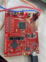
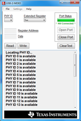
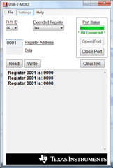
The USB-2-MDIO software seems to be able to read the PHY ID but not the register. The value of reading all registers is 0000, and the data waveform is measured when reading and writing. I want to ask where this problem is and how to solve it? Thank you very much!

  • Hello,

    Can you please provide the connection scheme from launchpad to PHY? It should be 4.1 = MDC, 4.2 = MDIO, with GNDs being connected.

    Sincerely,

    Gerome

  • Hello,

    I connected according to the instruction manual, P4.2 to MDC and P4.1 to MDIO. The connection is shown below

  • Hello,

    I swapped the connections of the two pins, again the same situation. Read other posts to change launchpad's 3.3V power supply to an external 2.1V voltage, using USB-2-MDIO to read and write registers is the same situation. Another is that all 32 PHY ids display "is available". According to my understanding, not all PHY ids can be used. It should be differentiated according to the hardware address, and only one can be recognized, right? Thank you very much for your help!(PDF is the configuration circuit diagram of the chip, looking at the chip manual of DP83867IR, it seems that RX_D0 to RX_D4 are hardware addresses that distinguish ids, but I am not completely clear yet. )Hope to get some help!

    Ether.pdf

  • Hello,

    While connections look good now per my prior communication, I would suggest the following:

    - VDDIO = 1.8V, so it would be advised to utilize a level shifter to get the PHY to talk to the MSP in the appropriate voltage. We have used TXS-EVM successfully in the past to talk to 1.8V designs. Changing the 3.3V supply to 2.1V *might* work, but is untested.

    - Ensure that PHY is powered on and connected to launchpad before launchpad is powered on

    Is the PHY able to link up? If the PHY is down, this could also explain why launchpad cannot detect it.

    Sincerely,

    Gerome

  • Hello,

    Follow the operation of powering up the launchpad after PHY is powered up and connected to the launchpad. The GUI still detects 32 PHY ids but it seems that each of them cannot read or write to the register, and the result is feedback 0000. I tried not connecting MDIO to MDC or launchpad to PHY but the IO voltage was below 2.1V, all 32 PHY ids were not available. Does this mean the launchpad is connected to the PHY? Why are 32 PHY ids available at the same time? Thank you very much!

  • Hello,

    This may be a byproduct of the awkward voltage domain workaround suggested in prior E2E queries. It is currently advised to utilize TXS-EVM for more robust operation of USB2MDIO when VDDIO is not 3.3V.

    Sincerely,

    Gerome

  • Hello,

    It seems that the launchpad is not detecting the PHY, as long as the launchpad is able to send the waveform, it will get the situation that all 32 ids are available. After measuring the communication waveform, it is found that the output waveform of launchpad is normal when the PHY is not connected. After connecting to the PHY, the high level of the output waveform of P4.2 pin of launchpad will be pulled down to about 400mv, and the waveform will become less pure. What might be the cause of this?

  • Hello,

    I bought a TXS0108E circuit module and built a 3.3v to 1.8v circuit. The MDC and MDIO of the launchpad and PHY are connected through this bidirectional level-conversion module. After testing, it is still the same as the initial situation. The output waveform at the PHY end, the 1.8V end, is also pulled down to around 700MV and seems to be affected and become cluttered.

  • Hello Gerome,

    I test the signal output waveform after suspending the three pins 54, 55 and 56 of DP83867 and find that the high level voltage of the signal has not been lowered. After passing the TXS level conversion circuit, it can communicate with the PHY. Would you like to ask whether disconnecting these three pins will affect the circuit? And now I try to configure 1000Mbps, RGMII mode, and then connect to the host computer through the network port through TCP/IP protocol. Configuring the register data according to the documentation does not seem to be successful, the host computer does not recognize the network cable. I would like to ask if there is a process for DP83867IR register mode configuration?Or some sample files.Thank you very much!

  • Hello,

    I understand that via the level shifter suggested, you are able to communicate with the PHY via registers. However, now you are getting link errors correct? If so, can you please provide a register dump of Reg 0x0-0x1F, as well as 0x6E/F. Please note these are extended registers (0x6E/F), but the USB2MDIO tool should take care of this for you inherently.

    I would also suggest to evaluate your design against our DP83867 schematic checklist located on the product page. This will assist with ensuring that everything from a design side looks good.

    Sincerely,

    Gerome

  • Hello,

    Thank you for your help, now it can be linked normally!

  • Hello,

    Can you please share what had to be corrected in your system to enable linkup? Perhaps this can assist other users in the future.

    Sincerely,

    Gerome

  • Hello,

    At that time the register did not write zero to the 7 bits of 0031.