DP83TC812EVM-MC: DP83TC812EVM-MC Register Programming through USB-2-MDIO

Part Number: DP83TC812EVM-MC

Tool/software:

Hello

     I am using DP83TC812EVM-MC in the following setup to detect SFD.

Packet generator (PC1)  => Ethernet cable  =>  EVM #1 =>  MATENet cable   => EVM#2   =>  Ethernet cable => PC2

The programming process described on Page 3 of the following document does not work for DP83TC812EVM-MC.

https://www.ti.com/lit/an/snla242/snla242.pdf?ts=1707858434919&ref_url=https%253A%252F%252Fwww.ti.com%252Fsitesearch%252Fen-us%252Fdocs%252Funiversalsearch.tsp%253FlangPref%253Den-US%2526searchTerm%253Dsfd%2Bieee%2B1588%2Btimestamp%2526nr%253D26

1. Could you Please let me know correct programming procedure ( registers and values) to detect SFD for DP83TC812EVM-MC for the above two EVMs setup.


Thanks

Krish

  • Hello Krish,

    I believe we were working on this topic already a few months ago: 

    https://e2e.ti.com/support/interface-group/interface/f/interface-forum/1320209/dp83tc812evm-mc-dp83tc812evm-mc-does-this-evm-support-sfd-ieee-1588-timestamp/5144574?tisearch=e2e-sitesearch&keymatch=%2520user%253A589945#5144574

    The correct programming procedure is given as well as a waveform. 

    Are there any updates or other questions you had on this?

    Regards,
    Avtar

  • HI Avtar

         I have 2 EVMs and MateNet. This is a new update.

    Few months ago, You said the following.

     " I used these registers: " 

    Register 0452 is: 0405
    Register 0452 is: 0504

    Question 1 :  I am not sure why the same register (0452) need to be written with two different values. ? 

    Question 2 : The following register programming does not work to transfer data between 2 PCs in the following setup.

    I used the basic PING command between two PCs with the following setup.

    PC1  => Ethernet cable  =>  EVM #1 =>  MATENet cable   => EVM#2   =>  Ethernet cable => PC2

    ////////////////////////////////////////////////////////////////////////////////////////////////////////////////////

    begin

    001f 8000 // restart core
    0000 2100 // force 100Mbps, full-duplex
    0010 5008 // 5008 - mdi , 5028 - mdix


    // Set the Device to output the SFD
    0172 0120

    // Set the Internal SFD Configuration.
    00E9 DF22

    // As per the snla242 document.
    //Enable enhanced receive features by writing 0x1080 to register 0x04A0
    //Configure the device to output the SFD's by writing 0x0406 to register 0x0452
    04A0 1080
    0452  0406    //  It does not match with what you said in your last post.


    // Apply Software Reset.
    001F 4000


    end

    //////////////////////////////////////////////////////////////////////////////////////////////////////////////////

    Pls, Let me know what correction need to be done in the above script  to communicate between two EVMs (  DP83TC812EVM-MC )

    Thanks

    Krish

  • Hello Krish,

    Question 1: In our data Sheet we have SFD for TX and RX , the registers are for TX and RX accordingly. 

    Question 2 :  I see this is in the script // As per the snla242 document., As I mentioned in the prior E2E that document and script is for the DP83867 and not the DP83TC812. 

    Regards,

    Avtar

  • Hi Avtar

    Let me know what correction need to be done in the  script that I sent for DP83TC812. ? 


  • Hello Krish,

    Below are the registers you will need to configure 

    Register 04A0  is  1080 (this will enable SFD detection)

    Register 0452 is: 0405 (setting LED0 for SFD TX)
    Register 0452 is: 0504 (setting LED0 for SFD RX)

    These are the only registers needed besides the normal phy operation registers.

    Regards,

    Avtar

  • Hi Avtar

          The register programming that you pointed out the last post did not help to send the basic "ping" command between two DP83TC812 EVMs.

    1. How do we set Master on EVM2 and  Slave on EVM2 ? 

    I did follow the following.  

    But, programming the following registers as you pointed out made the EVM boards to "hang"  

    Register 0452 is: 0405 (setting LED0 for SFD TX)
    Register 0452 is: 0504 (setting LED0 for SFD RX)

    2. Please Send me the complete script for Master EVM and complete script for slave EVM to make this ping command from PC1 to PC2 in the following setup.

    PC1  => Ethernet cable  =>  EVM #1 =>  MATENet cable   => EVM#2   =>  Ethernet cable => PC2

  • HI Avtar

           The master ( TX) and Slave (RX) should be configured through the following.  ( Not through Register 0452 which made the board to hang ).

    The following Answers from "Melissa Chang" helped to get the solution. 

    e2e.ti.com/.../dp83tc812evm-mc-media-converter-working

    Thank You.

  • Hello Krish,

    I am glad the master slave issue got resolved.

    Can you explain what happens when the EVM boards "hang" does this mean they become non functinoal?

    Also for complete script do you mean to write the ping command? If so these are related to whichever terminal you are using on your PC and you'll have to consult the PC provider. Typically in ipconfig or ifconfig you can set the ip address for both PC's and then type ping <ip address> . 

    Regards,

    Avtar 

  • HI Avtar

         I did not ask you for ping command :. We all know the ping command.  :-)

    I asked for the correct programming for the EVM board.   But, I figured it out  the EVM programming sequence and now everything works as expected.

    The following document is NOT applicable for programming DP83TC812 EVMs. 

    https://www.ti.com/lit/an/snla242/snla242.pdf?ts=1707858434919&ref_url=https%253A%252F%252Fwww.ti.com%252Fsitesearch%252Fen-us%252Fdocs%252Funiversalsearch.tsp%253FlangPref%253Den-US%2526searchTerm%253Dsfd%2Bieee%2B1588%2Btimestamp%2526nr%253D26

    In your earlier post, you suggested the Programming of the following registers to make TX and RX.   It  did not work and took so much time to debug.

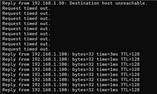
    See the screen shot that shows "timeout" when I used the following registers.  

    Register 0452 is: 0405 (setting LED0 for SFD TX)
    Register 0452 is: 0504 (setting LED0 for SFD RX)

    To make one EVM as Master and other EVM as Slave, the correct procedure is the following.

    Once I used this jumper at the correct pins, now the EVM1 works as Master and EVM2 works as Slave correctly.

    Here is the screen where the EVMs behaves as Master and Slave with the above procedure.

    Anyway, thanks for all your assistance so far.  !

  • Hello Krish,

    I am glad the issue is resolved, please let me know if you have any further questions. 

    Regards,
    Avtar