TFP401A-Q1: EMI issue

Part Number: TFP401A-Q1
Other Parts Discussed in Thread: TFP401

Tool/software:

Hi Sir,

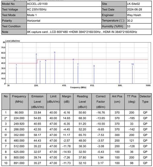
My customer tested the EMI performance for TFP401A-Q1, they got some test results over high at frequency bands of 224MHz and 352MHz.
Could you please help to review the schematics and PCB file to advise some comments to fix EMI issue? Thanks!

schematics and PCB file:

WF50B-0409.zip

  • Hey Henry,

    The next steps would be to isolate where the out of spec EMI frequencies are coming from; this could potentially be coming from harmonics of the frequency as well. You must look at the entire system when doing this and identify potential nets that may be the cause. Based off of the layout the TFP401 is the only high speed device on this board, and thus the EMI most likely is coming from the signal/ data pins on this device.

    My suggestions after finding the source of the EMI frequency would be to add common mode chokes (CMCs) to filter out emissions from the aggressor frequency. When picking a CMC for your system make sure the bandwidth is sufficient, and the proper frequencies are targeted. Placing a CMC on the incorrect net will not help the EMI performance of your PCB, so make sure you isolate and target the correct signal paths.

    Let me now if you have any questions.

    Best,

    Vishesh Pithadiya

  • Hi Sir,

    Could you also help to review the PCBA layout(the PCB file) is correct?

  • Hey Henry,

    On the layout we recommend each trace has a reference to ground as a current return path. Based off of the layout provided there are only two layers. I recommend moving to a four layer board with two ground planes in between the top and bottom layer. This lack of a current return path will also add onto the EMI issue.