This thread has been locked.

If you have a related question, please click the "Ask a related question" button in the top right corner. The newly created question will be automatically linked to this question.

DP83TC812EVM-MC: 100Base-T1 signal test

Part Number: DP83TC812EVM-MC

Tool/software:

hi team,

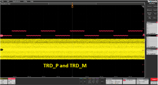
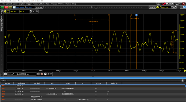
Can you provide the measured waveform of the 100Base-T1 of this evaluation board? The waveform I measured myself was poor!

  • Hi,

    I would suggest probing the 100Base-T1 signal using a differential probe across the TRD_M and TRD_P pins. 

    The signal should look like the yellow signal below at link up. 

    Best regards,

    Melissa

  • Hi I want to see   the   signal  details, could you please  Stretch the  timeline ? 

  • Hi,

    Why do you want to see the signal details? What is this for? Are you seeing an issue with the TI DP83TC812EVM?

    Best regards,

    Melissa

  • my  test result is poor, I want to  see  your  test result  as a compare,  I am not sure  the signal   I test whether is ok

  • Hi,

    Please confirm you are using a differential probe and measuring it across the connector output of the TRD_P and TRD_M pins.

    If you do not have a differential probe, you may use a single ended probe to measure TRD_P to GND in channel 1 and TRD_M to GND in channel 1 and perform a MATH function on the scope and do Channel1-Channel2.

    Best regards,

    Melissa

  • I measured it the way you said, wiht 3.5GHz  bandwidth    differential probe。 I want to  the signal  detail   you test   as  a contrast, wil you  provide it? thank you!

  • Hi,

    The expected waveform is shown above. Can you provide a photo of your waveform? Are you trying to measure the waveform for compliance? What is your application? 

    If there is a specific issue with your EVM, I’d be happy to help. 

    Best regards,

    Melissa 

  • hi   

    1.The expected waveform is shown above------ I can‘t see ’the TRD_P A&TRD_N  details

    2.Can you provide a photo of your waveform?---------A:  I has put my  waveform below my qustion  at  the begginning.

    3.Are you trying to measure the waveform for compliance? What is your application?---- I am testing the EVM board‘s’  TRD_PP&TRD_N  signal  Quality ,  I plan to  use  the PHY chip  for  our  new  design,  I should  make  sure this  PHY  chip  is no problem; I don't thik  there is  any issue   in the EVM ,I just want to see  the  RD_PP&TRD_N  signal  details  as  a contrast.


  • Hi,

    Im a little confused on what specific derails you require. The amplitude? The scale is shown in the photo if needed.

    Are you measuring the signal at linkup? Can you provide a photo of your probe?

    Best regards,

    Melissa