This thread has been locked.

If you have a related question, please click the "Ask a related question" button in the top right corner. The newly created question will be automatically linked to this question.

DP83869HM: The datasheet issue for DP83869HM

Part Number: DP83869HM
Other Parts Discussed in Thread: DP83869

Tool/software:

Hi,

We will use the DP83869HM for the Ethernet PHY, now, we have some issue for the datasheet description:

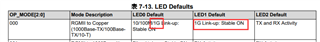
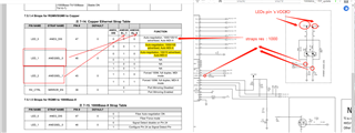
1. We read the datasheet 7.5.1.2 and 7.5.1.3, we want to know if the RGMII to copper is support 1000Base-TX or not?

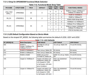
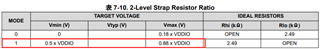
2. We read the datasheet, the LED1 IS 2-Level strap configuration, the TARGETVOL Vmin=0.5VDDIO, Vmax=0.88VDDIO when the MODE1;

   The PD=9Kohm based on the datasheet 7.5.1.2, 

   We Calculated the LED1 voltage as below:(The LED resistors Series with 470ohm and Resistors in Parallel with 2.49Kohm, the LED conduction resistance consider to 100ohm),

   Vled1= (9K/(470ohm+100ohm)//2.49Kohm+9K)*VDD=0.95VDD, 0.95VDD is morn than 0.88VDD, please kindly provide the principle of this design;

principle

3. Plesae kindly provde the RGMII RX_CLK Delay and TX_CLK Delay register or hardware configuration settings, or how to set the data that we can make sure the timing correctness? thanks.

  • Hi Zhang,

    1) This is a typo, DP83869 supports 1000Base-T, not TX. Apologies for the confusion here.

    2) Please assume higher series resistance for the LED in this example (1kohm).The strap values can be changed as needed depending on LED used.

    3) This will depend on the trace length to MAC, and if any delays are applied on the MAC side:

    https://e2e.ti.com/support/interface-group/interface/f/interface-forum/1099945/faq-how-to-select-correct-rgmii-delay-mode-for-phy-and-mac

    Delays can be configured in 0x32[1:0] (RGMII TX/RX shift/align modes) and 0x86[7:0] (TX/RX delay applied in shift mode).

    Thank you,

    Evan

  • Hi Evan,

    Thanks for your reply.

    For item# !) This is very fine, we are use the 1000Base-T for our design;

    For item#2) We also has the issue for the LED current because the VDDIO is support the 3.3V/ 2.5V/ 1.8V, based on our count, the voltage of the LED is very small because the 1Kohm divider resistor when the VDDIO is 1.8V/ 2.5V, we afraid the brightness of LED is very weak, so if there are any other suggest to make sure the 0.5 x VDDIO< Vtype <  0.88 x VDDIO, or we need to use the VDDIO=3.3V?

    BTW, we maybe find there is a error for the datasheet, for the table "7-13. LED Defaults", the LED0 default to "10/100M/1G Link-up: Stable ON" and LED1 default to "1G Link-up: Stable ON", so we have no idea if the "1G Link-up stable on" is judged by LED0 or LED1? This maybe confusing, please refer to below, 

  • Hi Zhang,

    Smaller series resistance LED can be used if LED brightness is a concern.

    For the LED chosen, please refer to Table 8-9 to calculate appropriate strap resistor values to ensure good margin between the VDDIO threshold for the mode chosen.

    Regarding LED0 and LED1 defaults for OP_MODE[2:0] = '000', both LED0 and LED1 will be stable on during 1G link case.

    Thank you,

    Evan

  • Hi Evan,

    We have finished the design for the DP83869HM and we have no idea if the RGMII need to signal grounding or not, the Guidelines of the datasheet has no descriptionfor this design, and our physical wiring and data wiring are of equal length is +/-5mil, thanks.

  • Hi Zhang,

    Solid ground plane under RGMII traces is recommended for impedance control.

    Please refer to this layout checklist for more detailed recommendations:

    https://www.ti.com/lit/zip/snlr048

    Thank you,

    Evan

  • Hi Evan,

    Please review our schematic diagram and check if there are any error, thanks.

    1000BASE_T PHY(2).pdf

  • Hi Zhang,

    Please fill out and return this schematic checklist ("Pin Wise Checklist" sheet): 

    https://www.ti.com/lit/zip/snlr051

    I can help review the schematic further after returning.

    Thank you,

    Evan

  • Hi Evan

    Please refer to the form, thanks.

    DP83869_Schematic_Checklist_phoskey_0810.xlsx

  • Hi Zhang,

    Thanks for returning the checklist, please see my feedback below:

    • Recommend adding 1Mohm resistor in parallel with C151 to help with isolation between connector and board grounds
    • What is the purpose of U6/U13? We typically discourage active components on MDI lines aside from magnetics, is this required for your system?
    • Device is strapped into RGMII to copper, this looks good
    • What is the estimated trace length for EXT_CLK to XI pin? We recommend shorter length here to maintain XI signal integrity
    • LEDs can use 2.5/3.3V supply if needed, but the required strap values will change. Please refer to Vmin/Vmax in table 7-10, the voltage sampled on the pin must be within the voltage range determined by VDDIO.
    • Can you clarify the status indicator requirements for link / TX-RX activity LEDs?

    Thank you,

    Evan

  • Hi Evan,

    Please refer to below:

    Recommend adding 1Mohm resistor in parallel with C151 to help with isolation between connector and board grounds

    We add the 1Mohm resistor parallel with C151;

    What is the purpose of U6/U13? We typically discourage active components on MDI lines aside from magnetics, is this required for your system?

    These are the TVS device, we refer to the PHY tomagnetics and SNLRO48A layout guidelines, please advise if we can add the TVS on this design?

    What is the estimated trace length for EXT_CLK to XI pin? We recommend shorter length here to maintain XI signal integrity

    For the trace of EXT_CLK  length, see the layout picture, it's only about 120mil(trace A + trace B):

    LEDs can use 2.5/3.3V supply if needed, but the required strap values will change. Please refer to Vmin/Vmax in table 7-10, the voltage sampled on the pin must be within the voltage range determined by VDDIO.

    We have updated the schematic diagram, +3V3_VCC_FPGA  is used  default , +2V5_VDDA is used alternative VCCIO, please confirm is there any error?

    Can you clarify the status indicator requirements for link / TX-RX activity LEDs?

    We consider to use the Auto-negotiation function mode, RGMII to copper mode, 

    1) The indicator LED_0 turn on when 1000BASE-T singal link speed good; 

    2) The indicator LED_1 turn on when the speed is changed with some cause link;

    3)  According to table 7-14, the R63, R65, R157 are used for the trap state resistors;

    BTW, how to configration in RGMII mode when the link speed can't achieve 1000base-T and these maybe only 100base-T or 10base-T?

    and how to get the right information from the LED on/off when only the 10Base or 100Base working condition? Thanks.

    The updated schematic please refer to attache, thanks.

    1000BASE_T PHY_updata.pdf

  • Hi Zhang,

    , please advise if we can add the TVS on this design

    This is acceptable, thanks for confirming.

    For the trace of EXT_CLK  length, see the layout picture, it's only about 120mil(trace A + trace B)

    Layout looks good here.

    We have updated the schematic diagram, +3V3_VCC_FPGA  is used  default , +2V5_VDDA is used alternative VCCIO, please confirm is there any error?

    Are different supplies required for each LED? I recommend using the same supply voltage for both so the resulting strap resistor calculations/values remain constant.

    1) The indicator LED_0 turn on when 1000BASE-T singal link speed good;

    Default LED_0 configuration is good for this, it will turn on during link in any speed.

    The indicator LED_1 turn on when the speed is changed with some cause link

    This condition is unclear to me. Does the desired interrupt condition fall within any condition listed below (register 0x18):

    BTW, how to configration in RGMII mode when the link speed can't achieve 1000base-T and these maybe only 100base-T or 10base-T?

    Referencing Table 7-14, strapping the LEDs to '000' will work in RGMII for 10/100/1000M, as the device will auto-negotiate to the highest available speed.

    and how to get the right information from the LED on/off when only the 10Base or 100Base working condition? Thanks.

    Please refer to register 0x18h. The LEDs can be configured to turn on for a specific link speed state.

    Thank you,

    Evan