Other Parts Discussed in Thread: DP83867E
Tool/software:
Thank you for your help.
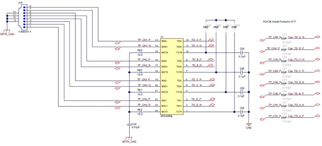
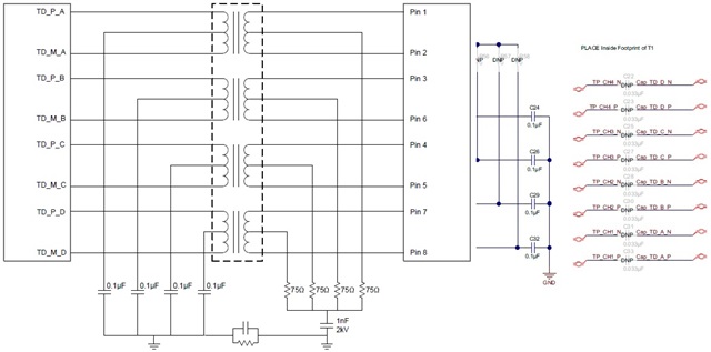
Please advise me on how to wire the MDI terminal and RJ45 terminal of this evaluation board.
RJ45 pinout (T568B standard)
1. Pin 1 (TX_D1+): White-orange
2. Pin 2 (TX_D1-): Orange
3. Pin 3 (TX_D2+): White-green
4. Pin 4 (TX_D3+): Blue
5. Pin 5 (TX_D3-): White-blue
6. Pin 6 (TX_D2-): Green
7. Pin 7 (TX_D4+): White-brown
8. Pin 8 (TX_D4-): Brown
DP83867E MDI terminal
1. Pin 1: TD_A_P: Positive signal of pair 1
2. Pin 2: TD_A_N: Negative signal of pair 1
3. Pin 4: TD_B_P: Positive signal of pair 2
4. Pin 5: TD_B_N: Negative signal of pair 2
5. Pin 7: TD_C_P: Positive signal of pair 3
6. Pin 8: TD_C_N: Negative signal of pair 3
7. Pin10: TD_D_P: Positive signal of pair 4
8. Pin11: TD_D_N: Negative signal of pair 4
T568B standard connection example
1. RJ45 pin 1 (TX_D1+): Pin1 TD_A_P of DP83867E
2. RJ45 pin 2 (TX_D1-): Pin2 TD_A_N of DP83867E
3. RJ45 pin 3 (TX_D2+): Pin4 TD_B_P of DP83867E
4. RJ45 pin 6 (TX_D2-): Pin5 TD_B_N of DP83867E
5. RJ45 pin 4 (TX_D3+): Pin7 TD_C_P of DP83867E
6. RJ45 pin 5 (TX_D3-): Pin8 TD_C_N of DP83867E
7. RJ45 pin 7 (TX_D4+): Pin10 TD_D_P of DP83867E
8. RJ45 pin 8 (TX_D4-): Pin11 TD_D_N of DP83867E
Evaluation board connection
1. RJ45 pin 1 (TX_D1+): Pin1 TD_D_P of DP83867E
2. RJ45 pin 2 (TX_D1-): Pin2 TD_D_N of DP83867E
3. RJ45 pin 3 (TX_D2+): Pin4 TD_C_P of DP83867E
4. RJ45 pin 6 (TX_D2-): Pin5 TD_C_N of DP83867E
5. RJ45 pin 4 (TX_D3+): Pin7 TD_B_P of DP83867E
6. RJ45 pin 5 (TX_D3-): Pin 8 TD_B_N of DP83867E
7. RJ45 pin 7 (TX_D4+): Pin 10 TD_A_P of DP83867E
8. RJ45 pin 8 (TX_D4-): Pin 11 TD_A_N of DP83867E
The MDI pair signal wiring of the evaluation board seems to be different from the standard connection example of the T568B standard, but should this pair wiring be taken into consideration in the actual design?
If possible, I would like to connect based on the T568B standard to ensure design consistency, but is there any problem?
Thank you in advance.


