This thread has been locked.

If you have a related question, please click the "Ask a related question" button in the top right corner. The newly created question will be automatically linked to this question.

DP83867IS: DP83867ISRGZ's LAN Compliance test is FAIL

Part Number: DP83867IS

Tool/software:

Dear TI

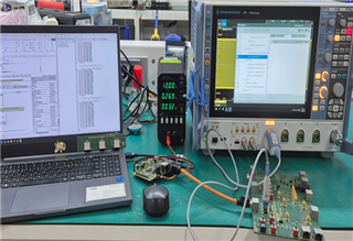
We changed the PCB design and conducted a new test.

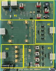
(There are two-PHY ICs on the PBA, LAN#0 & LAN#1)

Some failed.

Please guide me on the solution.

[Based on LAN Compliance]

(1) Problem#1(10Base-T) : w/ TPM level is 700mV. (w/o TPM level is 1.4V)

     -.Measure 2 items(Link Test Pulse)

          -->No TPM(14.3.1.2.1) item is PASS (LAN#0, LAN#1)

          -->With TPM(14.3.1.2.1) item is FAIL (LAN#0, LAN#1)

          --> I2C register :

                       mii write 0x0d 0x001F 0x8000
                         => mii write 0x0f 0x001F 0x8000
                         => mii write 0x0d 0x0000 0x0100
                         => mii write 0x0f 0x0000 0x0100
                         => mii write 0x0d 0x0010 0x5008
                         => mii write 0x0f 0x0010 0x5008

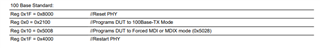
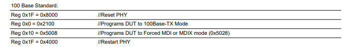
(2) Problem#2(100Base-T) : I tested it with Mode 5 and it failed. Any other setting?

     -.Measure 1 items(Return Loss) 

          -->Transmitter Returen Loss(9.1.5) item is PASS(LAN#0, LAN#1)

          -->Receiver Return Loss(9.2.2) item is FAIL(LAN#0, LAN#1)

          --> I2C register : (Test Mode 5)

                       mii write 0x0d 0x001F 0x8000
                         => mii write 0x0f 0x001F 0x8000
                         => mii write 0x0d 0x0000 0x2100
                         => mii write 0x0f 0x0000 0x2100
                         => mii write 0x0d 0x0010 0x5008
                         => mii write 0x0f 0x0010 0x5008
                         => mii write 0x0d 0x0009 0xBB00
                         => mii write 0x0f 0x0009 0xBB00
                         => mii write 0x0d 0x00D 0x001F
                         => mii write 0x0f 0x00D 0x001F
                         => mii write 0x0d 0x00E 0x0025
                         => mii write 0x0f 0x00E 0x0025
                         => mii write 0x0d 0x00D 0x401F
                         => mii write 0x0f 0x00D 0x401F
                         => mii write 0x0d 0x00E 0x0480
                         => mii write 0x0f 0x00E 0x0480

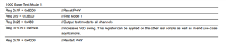
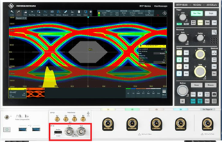
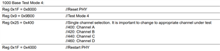
(3) Problem#3(1000Base-T) :  shortage of Margin 

          --> Differential Output Templates With Disturber's Point H is FAIL(LAN#1)

          --> I2C register : (Test Mode 1)

                       mii write 0x0d 0x001F 0x8000
                         => mii write 0x0f 0x001F 0x8000
                         => mii write 0x0d 0x0000 0x0140
                         => mii write 0x0f 0x0000 0x0140
                         => mii write 0x0d 0x0010 0x5008
                         => mii write 0x0f 0x0010 0x5008
                         => mii write 0x0d 0x0009 0x3B00
                         => mii write 0x0f 0x0009 0x3B00
                         => mii write 0x0d 0x00D 0x001F
                         => mii write 0x0f 0x00D 0x001F
                         => mii write 0x0d 0x00E 0x0025
                         => mii write 0x0f 0x00E 0x0025
                         => mii write 0x0d 0x00D 0x401F
                         => mii write 0x0f 0x00D 0x401F
                         => mii write 0x0d 0x00E 0x0480
                         => mii write 0x0f 0x00E 0x0480
                         => mii write 0x0d 0x00D 0x001F
                         => mii write 0x0f 0x00D 0x001F
                         => mii write 0x0d 0x00E 0x01D5
                         => mii write 0x0f 0x00E 0x01D5
                         => mii write 0x0d 0x00D 0x401F
                         => mii write 0x0f 0x00D 0x401F
                         => mii write 0x0d 0x00E 0xF508
                         => mii write 0x0f 0x00E 0xF508

  • Hi,

    Thank you for sharing the info. Here are some clarification I would like to mention for further debug:

    • May I get a clarification on what is the TPM you are referring to?
    • If possible, may I ask for a picture on how you test the compliance test? 
    • Could we also have a test failure test report that you see for compliance test?
    • Based on your register access, it seems like you are writing 0x000D and 0x000E two times. Just want to confirm one more time you are writing the extended register correctly, could you re-read the extended register value?

    --

    Regards,

    Hillman Lin

  • Hi,

    Please check the answer below.

    (1) May I get a clarification on what is the TPM you are referring to?

         -.Please check the "10Base-T.pdf" in the attached file.(LAN Compliance Test.zip)

         -.Onli "with TPM" of the same item fails.(It was not measured because the level was low.)

    LAN Compliance Test_240730.zip

    (2) If possible, may I ask for a picture on how you test the compliance test? 

         -.Test using R&S RTP equipment(with 1G Compliance S/W) and 1Gbit Test Fixture(ZF2).

         -.The mode setting is done with the PC.


    (3) Could we also have a test failure test report that you see for compliance test?

         -.Please refer to the attached zip-file of the item"(1)"

    (4) Based on your register access, it seems like you are writing 0x000D and 0x000E two times.

        Just want to confirm one more time you are writing the extended register correctly, could you re-read the extended register value?

         -.I captured the screen displayed on the PC.(Repeat twice)

         -.As I've said before, Two PHY ICs are installed in the PBA.

         -.What do you mean by an extension register? I have to ask the client company.

  • Hi Ryu,

    Thank you for sharing the information. I will discuss with the team and review the compliance report and provide you an response early next week.

    Thank you for your patience

    --

    Regards,

    Hillman Lin

  • Hi Ryu,

    Thank you for your patience.

    I discuss with the team on the test result. Here are some comments we would like to confirm with you.

    • For 1000Base-T Differential output. Did you use the following scrip:
      • If this script is the one you used, could you also try with only enabling the channel A and see if that help with your compliance result
    • For return loss test, It seems like you are seeing expected compliance result. Could you double check if you are using the correct script?
      • If possible, could you also take a photo on your current test fixture board and function generator waveform? We want to see how you test the return loss.

    --

    Thank you,

    Hillman Lin

  • Hi 

    This is an additional inquiry.

    please check the blue-text below

    (Please check the contents above again, and check the answer below)

    • For 1000Base-T Differential output. Did you use the following scrip:
      • If this script is the one you used, could you also try with only enabling the channel A and see if that help with your compliance result
      • -->(08/13) We write Regs at the same time in two-phy ics.
      •                 (In Test mode#1) I don't think I use Reg 0x1D5(=0x0F508).    
      •                 What's wrong with my register? 
    • For return loss test, It seems like you are seeing expected compliance result. Could you double check if you are using the correct script?
    •             -->(08/13) I used the same register.
    •                             Can I get a measurement photo of the receive-return loss item?                             
      • If possible, could you also take a photo on your current test fixture board and function generator waveform? We want to see how you test the return loss.
      • -->(08/13) As shown in the attached photo,It was measured by connecting to kit.
  • Hi Ryu,

    1. In some of the design, if customer cannot get an ideal compliance waveform. We recommend customer to use this register for their end application and see if this help with their compliance and get a bigger signal quality. We also recommend customer always use this register for compliance test. Are you able to see better compliance result with this register?
    2. Regarding to the photos, May I ask for a picture from the take from above? We want to make sure your fixture board (termination) and function generator are connected properly.

    --

    Regards,

    Hillman Lin

  • Hi,

    please check the below.

    1. My customer sets Register. I'll give you an answer soon.

    2. I will explain it with the image below.

       -.Connect the generator directly to the SMA in #3

       -.The Generator is built in to the oscilloscope.

       -.All tests are possible with RODHE's company RTP equipment.

    -->Only return-Loss requires additional equipment.(network analyzer)

    [Test Fixture]


    [OSC. equipment_RTP]

  • Hi Ryu,

    I talk with the team internally. It seems like your return loss test is not fully calibrated.

    One thing we would like to as you to test on the return loss are the following:

    • Could you try the return loss test with only 100ohms termination instead of connecting to the PHY and see if you are failing the return loss test? We want to check the background noise with perfect match of 100 ohms termination.

    --

    Regards,

    Hillman Lin

  • Hi,

    Thanks for your response

    Currently, we can't measure it because we don't have additional equipment.(Network Analyzer)

    At the time of measurement, only one of the two items in Return-Loss is fail

    (1) Transmitter Return Loss = PASS

    (2) Receive Return Loss = FAIL

    I wanted to know if two items(Tx, Rx Return Loss) are possible in the same settings.

    I wanted to know if I needed another Mode(Register) setting.

    What are the other answers(problem#1, #3) to the first question?

    please check it

  • Hi Ryu,

    Thank you for your patience

    We use this script for the return loss test:

    Currently, we are thinking the return loss test that you are currently measuring is not calibrated properly. The return loss failing level is too high based on your compliance result. Here are something that we would like to check for further debug:

    • Make sure you are probing the receiver channel
    • Making sure the return loss measurement is pre-calibrated correctly.

    --

    Regards,

    Hillman Lin

  • Hi,

    To measure the Return-Loss, do I have to apply the last register? (0x1F=0x4000)

    When I apply the last register(0x1F=0x4000),
    Doesn't the Register(0x2100,0x5008) applied to PHY get erased?

    Is the last register mandatory for testing?

  • Hi Ryu,

    Register 0x001F = 4000 is soft reset. It won't reset the register status.

    --

    Regards,

    Hillman Lin

  • Hi,

    please check it

    Can I understand that the last register(0x1F=0x4000) is mandatory for the LAN Compliance test?

  • Hi Ryu,

    Soft reset is good to have register for compliance test. 

    May I ask why you ask for 0x001F register? Are you not able to write it?

    I believe we are in a wrong direction. I would like to know the return loss measurement with 100 ohms termination before proceed further with the debug.

    --

    Regards,

    Hillman Lin

  • Hi.

    We tested it using a new board and register.

    There are 2 problems.(attachment pdf file)

    (1) 1000 Base-T, Point Template Test(w/ Disturbing Signal)

         -.Differences in performance by register(1000Base-T mode reg. 0x0140)

         --> Successful when inserting register, failed when removing register

    (2) 1000 Base-T, Transmitter Distortion(w/ Disturbing Signal)

         --> Workaround if only a particular pair fails (ex. D pair is fail)

    (3) There is a 125MHz(EMC) noise problem. We need a solution.

    please check it

    Eth0-1000-issue.pdf

  • Hi Ryu,

    Thank you for sharing the information.

    We talk with the team internally. The script you implemented for testing might be missing some information. Again sorry for the inconvience.

    Please refer to the follow script when you are performing compliance test:

    --

    Regards,

    Hillman Lin

  • Hi,

    How should I improve the two items? (2) & (3)

    (2) 1000 Base-T, Transmitter Distortion(w/ Disturbing Signal)

         --> Workaround if only a particular pair fails (ex. D pair is fail)

    (3) There is a 125MHz(EMC) noise problem. We need a solution.

    please check it


  • Hi Ryu,

    I possible, could you send us a schematic and layout file around the MDI lines. We would like to confirm if the board follow the checklist below:

    --

    Regards,

    Hillman Lin

  • Hi,

    To resolve 1000Base-T distortion...

    I'm sharing the data.

    Please reply after checking the contents.

    (TI attach)3113.Industrial_PHY_Layout Review Checklist.xlsx

  • Hi Ryu,

    I will take a look and provide you an response later.

    --

    Regards,

    Hillman Lin

  • Hi Ryu,

    Did you have any capacitor connected to ground on the MDI lines? If so, does removing those capacitors help with your distortion test?

    I did not see any center tap caps from the transformer or RJ45 connector. If possible, may I ask is those caps integrated inside the RJ45 shield?.

    Is the center tap of the transformer shorted to each others? This will also effect the distortion of the MDI lines

    --

    Regards,

    Hillman Lin

  • Hi,

    I'm sharing your response in the comments.

    please check it

    (1) Did you have any capacitor connected to ground on the MDI lines? If so, does removing those capacitors help with your distortion test?

    09/30 RYU) There is no cap on the MDI line.

                           When adding 100-ohms to the differential signal(between the two signals), It's getting worse.

    (2) I did not see any center tap caps from the transformer or RJ45 connector. If possible, may I ask is those caps integrated inside the RJ45 shield?.

    09/30 RYU) It's located inside. Attached is the data sheet.

    6712.48F-76NWZ2NL(REV1.1).pdf

    (3) Is the center tap of the transformer shorted to each others? This will also effect the distortion of the MDI lines

    09/30 RYU) Please refer to the data sheet.

                      I don't know the exact meaning."Is the center tap of the transformer shorted to each others?"

  • Hi Ryu,

    Thank you for sharing the information.

    May I ask for the new report that indicate channel D is failing? It seems like on the old report. Distortion test is passing. We would like to know what is the margin of the failure.

    If possible, could you enable mirror mode and see if the distortion test still fail on channel D?

    --

    Regards,

    Hillman Lin

  • Hi,

    Attached is the problematic report.

    There are also cases where all pairs are FAIL.

    1000Base-T_LAN2_distortion FAIL.pdf

    How do I apply mirror mode?

    (1) Change cable position?

    (2) Do I just need to add a register to the mode-4?

    please check it

  • Hi Ryu,

    Changing from straight cable to cross cable could and configure mirror mode by writing the register 0x0031.

    --

    Regards,

    Hillman Lin

  • Hi,

    Please check the attached file and test method.

    Look at the attached file results

    Report_2024_10_07_11_45_15.pdf

    1) Direct cable test detail : #1 to #4

    2) Cross cable test detail : #8 to #11 (mirror mode)

    3) I2C reg test method #1 : Measurement, but results fail

    [1000 Base Test Mode 4(0x0480)]
    mii write 0x0d 0x001F 0x8000
    mii write 0x0f 0x001F 0x8000
    mii write 0x0d 0x0000 0x0140
    mii write 0x0f 0x0000 0x0140
    mii write 0x0d 0x0010 0x5008
    mii write 0x0f 0x0010 0x5008
    mii write 0x0d 0x0009 0x9B00
    mii write 0x0f 0x0009 0x9B00
    mii write 0x0d 0x0031 0x0001
    mii write 0x0f 0x0031 0x0001
    mii write 0x0d 0x00D 0x001F
    mii write 0x0f 0x00D 0x001F
    mii write 0x0d 0x00E 0x0025
    mii write 0x0f 0x00E 0x0025
    mii write 0x0d 0x00D 0x401F
    mii write 0x0f 0x00D 0x401F
    mii write 0x0d 0x00E 0x0480
    mii write 0x0f 0x00E 0x0480

    4) I2C reg. test method #2 : Measurement fail

    mii write 0x0d 0x001F 0x8000
    mii write 0x0f 0x001F 0x8000
    mii write 0x0d 0x0009 0x9B00
    mii write 0x0f 0x0009 0x9B00
    mii write 0x0d 0x00D 0x001F
    mii write 0x0f 0x00D 0x001F
    mii write 0x0d 0x00E 0x0025
    mii write 0x0f 0x00E 0x0025
    mii write 0x0d 0x00D 0x401F
    mii write 0x0f 0x00D 0x401F
    mii write 0x0d 0x00E 0x0400
    mii write 0x0f 0x00E 0x0400
    mii write 0x0d 0x0031 0x0001
    mii write 0x0f 0x0031 0x0001
    mii write 0x0d 0x001F 0x4000
    mii write 0x0f 0x001F 0x4000

  • Hi Ryu,

    May I ask how many device are you seeing channel D failure issue? Have you test with other DP83867 and see the similar issue? 

    If possible, could you also add 10uF parallel on the Rbias pin and see if that help with the compliance performance. Want to make sure there are no signal path near the Rbias pin which effect the performance of the compliance test.

    --

    Regards,

    Hillman Lin

  • Hi,

    There are variations from PBA to PBA, but all channels(A/B/C/D pair) fail.

    And, only certain channels fail.

    Data measured with capacitor(10uF/10V) mounted.

    The same is a failure.

    Is distortion item related to bias?

    Report_2024_10_08_09_40_42.pdf

    please check it

  • 1) Direct cable test detail : #1 to #4

    2) Cross cable test detail : #8 to #11 (mirror mode)

    3) Direct cable test + Rbias(10uF) : #12 to #15

  • Hi Ryu,

    Thank you for the information.

    Let step back for a second and focus on the the scenario with channel D failure. Are you seeing any functional issue with the board you are current working on. Any link drop and any packets error during the communication? We are seeing a huge variation between the result you send before and after. If possible, could you also send us the transformer model that you are using. We want to make sure the functionality of the DP83867 is working first.

    We do have a discussion with the team internally. It seems that the capacitor value that could potentially help with the compliance result are the following:

    • 33pF parallel to the Rbias pin

    Again, sorry for the confusion. 33pF parallel to the Rbias pin is the capacitor value that could help with the compliance. 10uF capacitor value is too big and it won't have much effect on the compliance result.

    --

    Regards,

    Hillman lin

  • Hi,

    The answers are as follows.

    (1) Are you seeing any functional issue with the board you are current working on.

     -->241010 : There are no functional issues. However, we are not satisfied with the ETH compliance test.

    (2) We are seeing a huge variation between the result you send before and after. 

     -->241010 : There are variations from board to board. All pairs fail or one(or two) pairs fail.

    (3) If possible, could you also send us the transformer model that you are using. 

     -->241010 : Refer to the attached file(48F-76NWZ2NL(REV1.1).pdf)

    3175.48F-76NWZ2NL(REV1.1).pdf

    please check it

  • Hi Ryu,

    Good thing is you are not seeing functional issue on the PHY.

    Is it possible to have a smaller turn ratio tolerance and inductance for the transformer? Sometime the turn ratio mismatch of the transformer may potentially bring extra differential noise in the system. 

    Based on the internal discussion, we are able to see some marginality improvement by tuning the Rbias capacitor and Rbias value. If possible could you try the following test:

    • Add 33pF parallel to Rbias pin
    • Change Rbias value to 10kohms?

    --

    Regards,

    Hillman Lin

  • Hi,

    please check it

    (Please refer to Default report)

    (1) Default report : 

         i)Default : test report PDF #1 ~ #4(Rbias 11k-ohm)

         ii)Add 33pF parallel to Rbias pin : test report PDF #5 ~ #8

    ETH Report(Default_11kR_11kR+33pF).pdf

    (2) The test results are as follows : 

         i)Add 33pF parallel to Rbias pin : test report PDF #5 ~ #8

         ii)Change Rbias value to 10kohms? : test report PDF #1 ~ #4 (with 33pF)

    Report_2024_10_11_09_47_14.pdf

  • This is an additional review

    Lowering the Rbias value improved performance.

    Can other ETH compliance items fail depending on the Rbias value?

    please check it

    (1) Default report : 

         i)Default : test report PDF #1 ~ #4(Rbias 11k-ohm)

         ii)Add 33pF parallel to Rbias pin : test report PDF #5 ~ #8

         iii)Change Rbias value : 11kohm --> 6.8kohm #9 ~ #12

         iiii)Change Rbias value : 6.8kohm --> 4.3kohm #13 ~ #16

         v)Change Rbias value : 4.3kohm --> 1.8kohm #17 ~ #20

    ETH Report(Default_11kR_11kR+33pF_6.8kR_4.3kR_1.8kR).pdf

  • Hi Ryu,

    Thank you for investing time on debugging this issue together.

    We only validate the Rbias value down to 9k ohms. Based on your test setup, our recommendation is using 9kohms //33pF on the Rbias pin.

    We discuss with the team internally. We did not see this kind of big distortion failure before with DP83867. There are some possible reason that might need result in this kind of failure on the distortion compliance test:

    • If possible, could you check the jitter and the PPM on the clock signal? Making sure the clock signal is clean
    • Check if the power rail input to the PHY is clean, There shouldn't be a lot of ripple on the power rail
    • Check if there are no external noise effecting the Rbias pin. Rbias pin is always stable at constant DC voltage

    --

    Regards,

    Hillman Lin