DS90UB948-Q1EVM: DS90UB948-Q1

Part Number: DS90UB948-Q1EVM
Other Parts Discussed in Thread: ALP, DS90UB947-Q1EVM, USB2ANY

Tool/software:

Hi, 

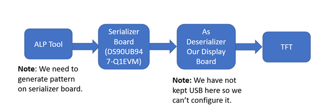
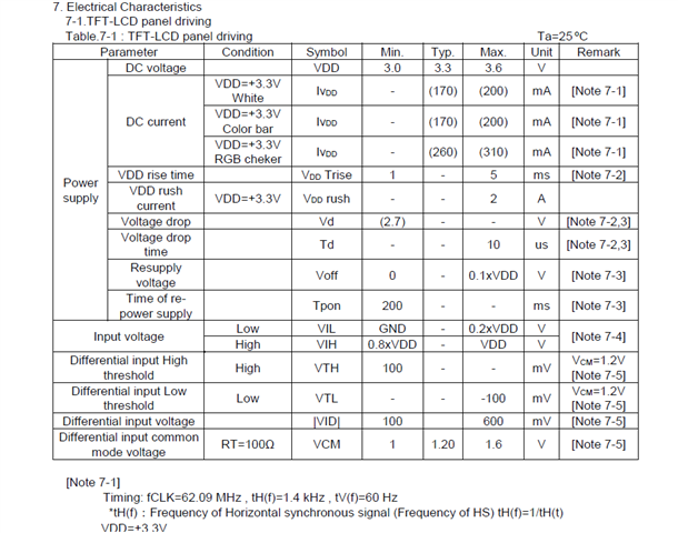
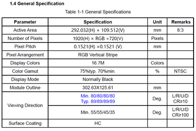
->We are currently working on a display board which can run 12.5" inch TFT.

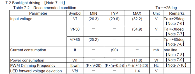
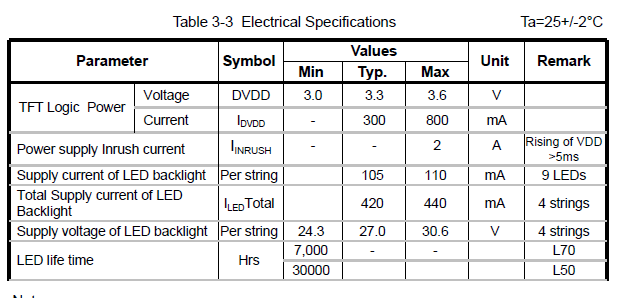
->We have attained the backlight driver voltages. Power section is fine. But we are not getting anything  or any visuals on TFT. 

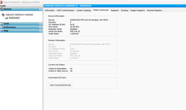
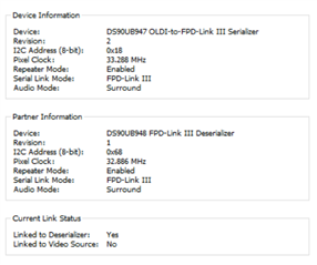
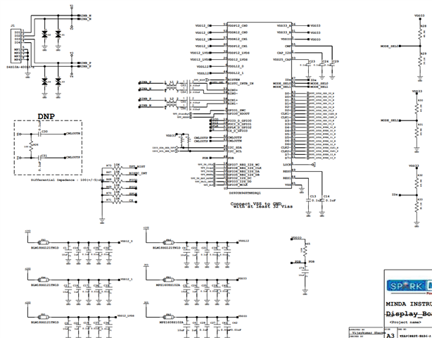
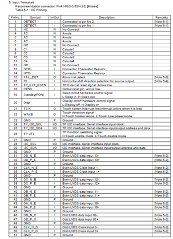
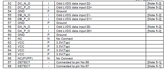
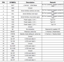
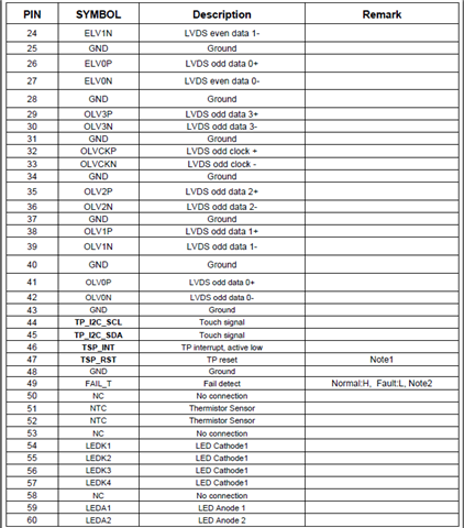
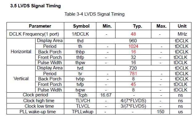
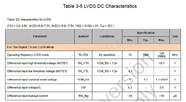
->We checked  the LVDS signals and control signals which are coming out from the deserializer. But we are not sure what that signals are in actual terms.

->We have used the TI SerDes Eval Kit in which we used serializer eval board and used deserializer board of ours and also dumped resistor data into our deserializer board. 

->Now further what is a necessary step and action we should carry out so that we can attain the output.

->Also is there any tutorial or training for pattern generation in ALP tool? Kindly let me know.

Regards.

Fazil P

  • Hi Fazil,

    Happy to provide support on this matter. Some follow-up questions:

    • What serializer EVM board is being utilized?
    • Have you attempted PATGEN from the serializer or deserializer? Or both?

    There is no specific tutorial for the Pattern Generator tab in ALP. Do you have any specific questions? And can you provide a screen capture of what your Pattern Generator tab looks like when trying to bring up the display?

    Best,

    Nikolas

  • Hi Nikolas,

    We are using DS90UB947-Q1EVM FPD LINK III Serializer Eval Board.

    We have tried to attempt PATGEN from serializer only. Also we are using our display board as deserializer and we have not given a USB port to it so we can't connect that. 

    Here I have attached a image of the Pattern Generator Tab.

    Regards, 

    Fazil P

  • Hi Fazil,

    Two things of note:

    1. The wrong ALP profile is selected
    2. The downstream partner device is not detected

    To select the correct ALP profile, please navigate to to Tools --> USB2ANY/Aardvark Setup --> Remove the DS90UH925 Profile -->  Add the DS90UB947 Profile. Once this step is complete, you should see an Information tab that looks like this, with DS90UB947 listed as the device DS90UB948 listed as the partner device.

    Note that if the DS90UB948 is not detected as the partner device, then enabling PATGEN from the 947 will not work, so the 948 must be detected before proceeding to the next step. 

    Once you have the devices detected properly, you can then navigate to the Pattern Generator tab (sometimes you must go from the Patgen Registers tab to the Pattern Generator tab in order for the tab to populate correctly). The Pattern Generator tab looks like this:

    On this tab, you can configure your pattern accordingly and press "Apply" when ready. 

    Best,

    Nikolas

  • Hi Nikolas,

    We have successfully interface the SerDes and it is showing in ALP tool also, but still we are not able to generate the Pattern.

  • Hi Fazil,

    Can you please provide a screenshot of your Pattern Generator tab with the desired pattern configurations? I would like to generate a script for you based on those configurations to be run on your EVM and see if it brings up the pattern.

    Best,

    Nikolas

  • Hi Nicolas,

    I have tried multiple inputs for pattern generator from my side as per my assumptions and knowledge.

    So I have a request that will it be possible that I provide you the characteristics data of the TFT I have. ? 

    And further you can help with creating a script with this data. That will be a easy option I guess. And directly we can reach to a solution.

    Herewith I have attached some parameters that can be useful for the script generation part.

    If anything else is required for generating script , then kindly let me know.

    Regards,

    Fazil P

  • Hi Nicolas,

    This is the actual scenario. Just for your reference . If it helps.

    Regards,

    Fazil P

  • Hi Fazil,

    Thank you for sharing the block diagram - it was not previously established that the panel was a TFT display. What should first be established is if the panel can accept the video output coming from the 948 - what may be happening is the 947 is programming the pattern accordingly and sending it to the 948, but no pattern is displayed on the panel because it cannot accept the 948 video datatype.

    Does the TFT panel have an OLDI input? In addition, do you have access to the 948 schematic, specifically its OLDI output pins?

    Best,

    Nikolas

  • Hi Nicolas,

    Yes there are LVDS signals coming to TFT. But that signals actually are not accepted by TFT as per your statement.

    Also we have the schematics for 948.

    For your reference here we will attach schematics image.

    If anything else is required, Kindly let me know.

    Regards,

    Fazil P

  • Hi Fazil,

    Yes there are LVDS signals coming to TFT. But that signals actually are not accepted by TFT as per your statement.

    I am not too sure I follow this statement. Are you saying the display is not capable of accepting LVDS signals? If possible, please provide the datasheet for the display.

    Best,

    Nikolas

  • Hi Nicolas,

    As per some protocols I will not be able to share whole Datasheet but can surely provide whatever parameters are required through images of the datasheet.

    Herewith I have attached some images for your reference.

    Regards,

    Fazil P

  • Hi Nicolas,

    Also if any other parameter is required then kindly let me know.

    Regards,

    Fazil P

  • Hi Fazil,

    It seems that there may be a PCLK mismatch here. Based on the diplay timing specifications, a PCLK of ~82.94 MHz (1920*720*60) is needed. However, looking at the ALP screenshot you provided, both the 947 and 948 are currently configured for PCLKs of ~33MHz. This PCLK mismatch could contribute to the black screen. Please ensure that the PCLKs across both devices matches the timing of the display.

    Best, 

    Nikolas

  • Hi Nicolas, 

    We have checked the necessity of PCLK's and it fulfils the requirement.

    Also we have a request that can you please share your email address so that we can share required documents to you without any issue.

    Because we have already signed a NDA with TI. So documents sharing on mails wont be a issue.

    Regards,

    Fazil P

  • Hi Fazil,

    The Pattern Generator tab can only program four pre-selected approximate PCLKs based on the default internal REFCLK of 200MHz. To get closer to the PCLK of the display timings, the internal oscillator frequency must be changed to 800MHz and the M/N divider must be adjusted accordingly (PCLK = Oscillator Frequency * (M/N)). The internal reference oscillator frequency is multiplied by the M/N ratio to determine the desired PCLK. If an 800MHz clock is selected, with an M value of 3 and an N value of 29, then PCLK = 800MHz * (3/29) = ~82.75MHz.

    I am attaching a script to this thread that programs a pattern with the PCLK accounted for. Can you try running this script in the 947 ALP Profile via the "Scripting" tab and let me know if it successfully brings up the pattern? Note that a default SER address of 0x18 was selected - if this is not the strapped IDX address then please adjust this value accordingly. 

    Best,

    Nikolas

    serAddr = 0x18
    PGIA = 0x66
    PGID = 0x67
    
    board.WriteI2C(serAddr, PGIA, 0x00)
    board.WriteI2C(serAddr, PGID, 0x00) #PGRS
    board.WriteI2C(serAddr, PGIA, 0x01)
    board.WriteI2C(serAddr, PGID, 0x00) #PGGS
    board.WriteI2C(serAddr, PGIA, 0x02)
    board.WriteI2C(serAddr, PGID, 0x00) #PGBS
    board.WriteI2C(serAddr, PGIA, 0x03)
    board.WriteI2C(serAddr, PGID, 0x29) #PGCDC1
    board.WriteI2C(serAddr, PGIA, 0x04)
    board.WriteI2C(serAddr, PGID, 0x7f) #PGTFS1
    board.WriteI2C(serAddr, PGIA, 0x05)
    board.WriteI2C(serAddr, PGID, 0x39) #PGTFS2
    board.WriteI2C(serAddr, PGIA, 0x06)
    board.WriteI2C(serAddr, PGID, 0x2f) #PGTFS3
    board.WriteI2C(serAddr, PGIA, 0x07)
    board.WriteI2C(serAddr, PGID, 0x80) #PGAFS1
    board.WriteI2C(serAddr, PGIA, 0x08)
    board.WriteI2C(serAddr, PGID, 0x07) #PGAFS2
    board.WriteI2C(serAddr, PGIA, 0x09)
    board.WriteI2C(serAddr, PGID, 0x2d) #PGAFS3
    board.WriteI2C(serAddr, PGIA, 0x0a)
    board.WriteI2C(serAddr, PGID, 0x60) #PGHSW
    board.WriteI2C(serAddr, PGIA, 0x0b)
    board.WriteI2C(serAddr, PGID, 0x03) #PGVSW
    board.WriteI2C(serAddr, PGIA, 0x0c)
    board.WriteI2C(serAddr, PGID, 0xff) #PGHBP
    board.WriteI2C(serAddr, PGIA, 0x0d) 
    board.WriteI2C(serAddr, PGID, 0x0a) #PGVBP
    board.WriteI2C(serAddr, PGIA, 0x0e)
    board.WriteI2C(serAddr, PGID, 0x00) #PBSC
    board.WriteI2C(serAddr, PGIA, 0x0f)
    board.WriteI2C(serAddr, PGID, 0x1e) #PGFT
    board.WriteI2C(serAddr, PGIA, 0x10)
    board.WriteI2C(serAddr, PGID, 0x0c) #PGTSC
    board.WriteI2C(serAddr, PGIA, 0x11)
    board.WriteI2C(serAddr, PGID, 0x21) #PGTS01
    board.WriteI2C(serAddr, PGIA, 0x12)
    board.WriteI2C(serAddr, PGID, 0x43) #PGTS02
    board.WriteI2C(serAddr, PGIA, 0x13)
    board.WriteI2C(serAddr, PGID, 0x65) #PGTS03
    board.WriteI2C(serAddr, PGIA, 0x14)
    board.WriteI2C(serAddr, PGID, 0x87) #PGTS04
    board.WriteI2C(serAddr, PGIA, 0x15)
    board.WriteI2C(serAddr, PGID, 0xa9) #PGTS05
    board.WriteI2C(serAddr, PGIA, 0x16)
    board.WriteI2C(serAddr, PGID, 0xcb) #PGTS06
    board.WriteI2C(serAddr, PGIA, 0x17)
    board.WriteI2C(serAddr, PGID, 0xed) #PGTS07
    board.WriteI2C(serAddr, PGIA, 0x18)
    board.WriteI2C(serAddr, PGID, 0x0f) #PGTS08
    board.WriteI2C(serAddr, PGIA, 0x19)
    board.WriteI2C(serAddr, PGID, 0x00) #PGBE
    board.WriteI2C(serAddr, PGIA, 0x1a)
    board.WriteI2C(serAddr, PGID, 0x03) #PGCDC2
    
    board.WriteI2C(serAddr, 0x65, 0x00)
    board.WriteI2C(serAddr, 0x64, 0x05)

  • Hi Nicolas,

    We tried to implement the script, but still there is no output seen on the display. 

    Can we know how to set the Patgen registers manually.

    One question to you, That is there is convention to send any command or control signals to TFT?

    Is it required to control this command signals to TFT to achieve pattern generator?

    Regards,

    Fazil P

  • Hi Fazil,

    Can we know how to set the Patgen registers manually.

    For more information, I would suggest referring to the following app note: SNLA132. Please let me know if you are able to successfully bring-up a pattern using the guidance in the application note and if so, what differed between the previously provided script and the script that worked.

    One question to you, That is there is convention to send any command or control signals to TFT?

    Is it required to control this command signals to TFT to achieve pattern generator?

    I am not too sure I follow this set of questions. Could you possibly re-phrase?

    Best,

    Nikolas

  • Hi Nicolas,

    We have checked all the possibilities from the suggestions given. But we are at the same place.

    We have got a new TFT at our place. Will share some screenshots for the same.

    Can you please share the script for the same.

    Below are the screenshots.

    If these are sufficient then kindly provide the script so I can try my deserializer board this TFT.

    Regards,

    Fazil P

  • Hi Fazil,

    I can generate new scripts, but need two additional pieces of information: 1) what is the refresh rate of the display in Hz? and 2) what polarity does the display require for HSYNC and VSYNC?

    Once I have that information, I can generate two new scripts: one that generates a pattern from the 947 and one that generates a pattern from the 948. Depending on if both/one/neither of the scripts successfully bring up the pattern, we can proceed forward accordingly. If neither script works, the next logical steps will be as followed:

    1. Monitor the LOCK pin on the 948 to confirm that it is stable and not intermittently lost.
    2. Review the LVDS connections between the 948 DES board and TFT display to confirm they are correct, then running the attached 948 DES PATGEN script. 
      1. If pattern is not brought up after (2), then issue lies somewhere within the 948 DES board or TFT displays.
      2. If pattern is brought up after (2), then issue lies somewhere within the 947 SER EVM or between the 948 DES board and 947 SER EVM.

    Depending on the results of the above actions, we can cater this bring-up accordingly to the proper "blocks" of the system.

    Best,

    Nikolas

  • Hi Nikolas,

    1)The refresh rate of the display is 60hz.

    2)The datasheet indicates that the display operates in Data Enable (DE) mode. However, if HSYNC and VSYNC signals are used, they typically require Negative polarity (active low) as per display standards.

    Regards,

    Mayank B

  • Hello,

    Okay, please allow me 1-2 business days to generate the script. Note that there is a US holiday on Monday, Sept 2.

    Best,

    Nikolas

  • Hi Nikolas,

    Okay. 

    Regards,

    Fazil P

  • Hello Fazil,

    The team is currently out of office due to the US public holiday and will resume activity on 9/3. Thank you for your patience during this time 

    Best Regards,

    Casey 

  • Hello,

    Okay. No worries.

    Regards,

    Fazil P

  • Hi Fazil,

    Please see below for two new PATGEN scripts - one that enables PATGEN from the 947 and one that enables PATGEN from the 948, both with negative polarity for sync widths. Can you try running this script in the 947 ALP Profile via the "Scripting" tab and let me know if it successfully brings up the pattern? Note that a default SER address and DES address of 0x18 and 0x58 were selected, respectively. If these are not the strapped IDX address then please adjust these values accordingly. 

    Best,

    Nikolas

    serAddr = 0x18
    PGIA = 0x66
    PGID = 0x67
    
    board.WriteI2C(serAddr, PGIA, 0x00)
    board.WriteI2C(serAddr, PGID, 0x00) #PGRS
    board.WriteI2C(serAddr, PGIA, 0x01)
    board.WriteI2C(serAddr, PGID, 0x00) #PGGS
    board.WriteI2C(serAddr, PGIA, 0x02)
    board.WriteI2C(serAddr, PGID, 0x00) #PGBS
    board.WriteI2C(serAddr, PGIA, 0x03)
    board.WriteI2C(serAddr, PGID, 0x29) #PGCDC1
    board.WriteI2C(serAddr, PGIA, 0x04)
    board.WriteI2C(serAddr, PGID, 0x7f) #PGTFS1
    board.WriteI2C(serAddr, PGIA, 0x05)
    board.WriteI2C(serAddr, PGID, 0x39) #PGTFS2
    board.WriteI2C(serAddr, PGIA, 0x06)
    board.WriteI2C(serAddr, PGID, 0x2f) #PGTFS3
    board.WriteI2C(serAddr, PGIA, 0x07)
    board.WriteI2C(serAddr, PGID, 0x80) #PGAFS1
    board.WriteI2C(serAddr, PGIA, 0x08)
    board.WriteI2C(serAddr, PGID, 0x07) #PGAFS2
    board.WriteI2C(serAddr, PGIA, 0x09)
    board.WriteI2C(serAddr, PGID, 0x2d) #PGAFS3
    board.WriteI2C(serAddr, PGIA, 0x0a)
    board.WriteI2C(serAddr, PGID, 0x60) #PGHSW
    board.WriteI2C(serAddr, PGIA, 0x0b)
    board.WriteI2C(serAddr, PGID, 0x03) #PGVSW
    board.WriteI2C(serAddr, PGIA, 0x0c)
    board.WriteI2C(serAddr, PGID, 0xff) #PGHBP
    board.WriteI2C(serAddr, PGIA, 0x0d) 
    board.WriteI2C(serAddr, PGID, 0x0a) #PGVBP
    board.WriteI2C(serAddr, PGIA, 0x0e)
    board.WriteI2C(serAddr, PGID, 0x03) #PBSC, sets NEGATIVE polarity
    board.WriteI2C(serAddr, PGIA, 0x0f)
    board.WriteI2C(serAddr, PGID, 0x1e) #PGFT
    board.WriteI2C(serAddr, PGIA, 0x10)
    board.WriteI2C(serAddr, PGID, 0x0c) #PGTSC
    board.WriteI2C(serAddr, PGIA, 0x11)
    board.WriteI2C(serAddr, PGID, 0x21) #PGTS01
    board.WriteI2C(serAddr, PGIA, 0x12)
    board.WriteI2C(serAddr, PGID, 0x43) #PGTS02
    board.WriteI2C(serAddr, PGIA, 0x13)
    board.WriteI2C(serAddr, PGID, 0x65) #PGTS03
    board.WriteI2C(serAddr, PGIA, 0x14)
    board.WriteI2C(serAddr, PGID, 0x87) #PGTS04
    board.WriteI2C(serAddr, PGIA, 0x15)
    board.WriteI2C(serAddr, PGID, 0xa9) #PGTS05
    board.WriteI2C(serAddr, PGIA, 0x16)
    board.WriteI2C(serAddr, PGID, 0xcb) #PGTS06
    board.WriteI2C(serAddr, PGIA, 0x17)
    board.WriteI2C(serAddr, PGID, 0xed) #PGTS07
    board.WriteI2C(serAddr, PGIA, 0x18)
    board.WriteI2C(serAddr, PGID, 0x0f) #PGTS08
    board.WriteI2C(serAddr, PGIA, 0x19)
    board.WriteI2C(serAddr, PGID, 0x00) #PGBE
    board.WriteI2C(serAddr, PGIA, 0x1a)
    board.WriteI2C(serAddr, PGID, 0x03) #PGCDC2
    
    board.WriteI2C(serAddr, 0x65, 0x00)
    board.WriteI2C(serAddr, 0x64, 0x05)

    desAddr = 0x58
    PGIA = 0x66
    PGID = 0x67
    
    board.WriteI2C(desAddr, PGIA, 0x00)
    board.WriteI2C(desAddr, PGID, 0x00) #PGRS
    board.WriteI2C(desAddr, PGIA, 0x01)
    board.WriteI2C(desAddr, PGID, 0x00) #PGGS
    board.WriteI2C(desAddr, PGIA, 0x02)
    board.WriteI2C(desAddr, PGID, 0x00) #PGBS
    board.WriteI2C(desAddr, PGIA, 0x03)
    board.WriteI2C(desAddr, PGID, 0x29) #PGCDC1
    board.WriteI2C(desAddr, PGIA, 0x04)
    board.WriteI2C(desAddr, PGID, 0x7f) #PGTFS1
    board.WriteI2C(desAddr, PGIA, 0x05)
    board.WriteI2C(desAddr, PGID, 0x39) #PGTFS2
    board.WriteI2C(desAddr, PGIA, 0x06)
    board.WriteI2C(desAddr, PGID, 0x2f) #PGTFS3
    board.WriteI2C(desAddr, PGIA, 0x07)
    board.WriteI2C(desAddr, PGID, 0x80) #PGAFS1
    board.WriteI2C(desAddr, PGIA, 0x08)
    board.WriteI2C(desAddr, PGID, 0x07) #PGAFS2
    board.WriteI2C(desAddr, PGIA, 0x09)
    board.WriteI2C(desAddr, PGID, 0x2d) #PGAFS3
    board.WriteI2C(desAddr, PGIA, 0x0a)
    board.WriteI2C(desAddr, PGID, 0x60) #PGHSW
    board.WriteI2C(desAddr, PGIA, 0x0b)
    board.WriteI2C(desAddr, PGID, 0x03) #PGVSW
    board.WriteI2C(desAddr, PGIA, 0x0c)
    board.WriteI2C(desAddr, PGID, 0xff) #PGHBP
    board.WriteI2C(desAddr, PGIA, 0x0d) 
    board.WriteI2C(desAddr, PGID, 0x0a) #PGVBP
    board.WriteI2C(desAddr, PGIA, 0x0e)
    board.WriteI2C(desAddr, PGID, 0x03) #PBSC, sets NEGATIVE polarity
    board.WriteI2C(desAddr, PGIA, 0x0f)
    board.WriteI2C(desAddr, PGID, 0x1e) #PGFT
    board.WriteI2C(desAddr, PGIA, 0x10)
    board.WriteI2C(desAddr, PGID, 0x0c) #PGTSC
    board.WriteI2C(desAddr, PGIA, 0x11)
    board.WriteI2C(desAddr, PGID, 0x21) #PGTS01
    board.WriteI2C(desAddr, PGIA, 0x12)
    board.WriteI2C(desAddr, PGID, 0x43) #PGTS02
    board.WriteI2C(desAddr, PGIA, 0x13)
    board.WriteI2C(desAddr, PGID, 0x65) #PGTS03
    board.WriteI2C(desAddr, PGIA, 0x14)
    board.WriteI2C(desAddr, PGID, 0x87) #PGTS04
    board.WriteI2C(desAddr, PGIA, 0x15)
    board.WriteI2C(desAddr, PGID, 0xa9) #PGTS05
    board.WriteI2C(desAddr, PGIA, 0x16)
    board.WriteI2C(desAddr, PGID, 0xcb) #PGTS06
    board.WriteI2C(desAddr, PGIA, 0x17)
    board.WriteI2C(desAddr, PGID, 0xed) #PGTS07
    board.WriteI2C(desAddr, PGIA, 0x18)
    board.WriteI2C(desAddr, PGID, 0x0f) #PGTS08
    board.WriteI2C(desAddr, PGIA, 0x19)
    board.WriteI2C(desAddr, PGID, 0x00) #PGBE
    board.WriteI2C(desAddr, PGIA, 0x1a)
    board.WriteI2C(desAddr, PGID, 0x03) #PGCDC2
    
    board.WriteI2C(desAddr, 0x65, 0x00)
    board.WriteI2C(desAddr, 0x64, 0x05)