DP83869HM: Unmanaged 1000M Media Converter Application

Part Number: DP83869HM
Other Parts Discussed in Thread: DP83869, DP83869EVM

Tool/software:

Hi

I am designing a product that need a 1000BASE-SX interface.

The computer board I must use has a 10/100/1000/2500MBit copper ethernet interface.

Because of this I intend to use the DP83869HM in the 1000M Media Converter application mode.

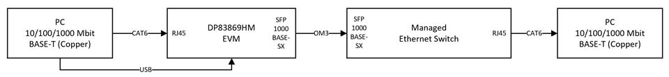
My intended setup is as follows:

10/100/1000/2500MBit copper -> DP83869HM in 1000M Media Converter mode -> 1000BASE-SX SFP -> External Link Partner (during testing I will simulate the LP with an ethernet switch (managed type) with an SFP port).

My goal is to run the DP83869HM in unmanaged mode. I am not planning to use an MCU controller for this product.

I want to force the MAC on the computer side to run at fixed 1000Mbps. The fiber SFP transceiver will run at 1000Mbps.

Can you confirm that the following approach is valid? If anything is missing or wrong, please let me know.
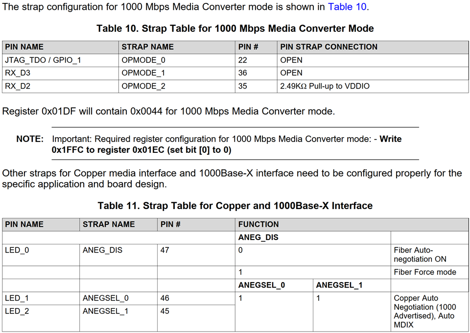
Straps

PHY ADDR set to 0 (single PHY on the bus) -> PHY_AD[3]:PHY_AD[0] all set to 0

Operation mode:1000M Media Converter -> OPMODE_2 = 1, OPMODE_1 = 0 and OPMODE_0 = 0 -> On EVM: OPMODE_2 = PU (J19 shorted), OPMODE_1 = PD (J10 open) and OPMODE_0 = PD (J11 open).

ANEG_DIS set to 1 to disable auto-negotiation on fiber side and force 1000Mbps -> On EVM: J2 = PU (J2 jumper placed between pins 2 and 3)

ANEGSEL_1 and ANEGSEL_0 both set to 1 to force 1000Mbps between DP83869HM and PC Ethernet MAC (during auto-negotiation) -> On EVM: J4 = PU (J4 jumper placed between pins 2 and 3) and J7 = PU (J4 jumper placed between pins 2 and 3).

MIRROR_EN disabled -> On EVM: MIRROR_EN = PD (J8 open)

LINK_LOSS pass through enabled -> On EVM: LINK_LOSS = PD (J6 open)

However, in app note SNLA318 the following is mentioned on page 8:

NOTE: Important: Required register configuration for 1000 Mbps Media Converter mode: - Write
0x1FFC to register 0x01EC (set bit [0] to 0)

In my opinion, requiring a register write goes against the unmanaged mode.

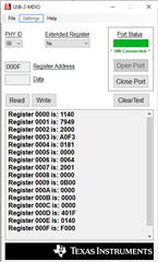
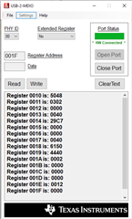
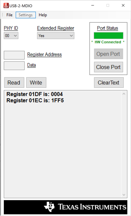
I have tried to test the straps mentioned above on the EVM and I read the following using the USB-to-MDIO tool:

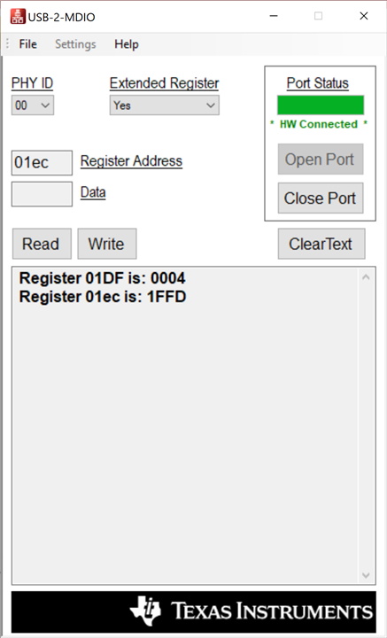
If I short J6 on the EVM I read the following:

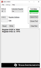
This does change the value of the register, but not bit 0. Instead, it writes bit 3 to 0.

How should I proceed? Is the LINK_LOSS strap tied to bit 0 in register 0x01EC (CFG_NO_LINK_LINK_LOSS_EN)?

The datasheet specifies the default value for the LINK_LOSS strap to be 0, i.e. enabled, so I would think that the pin RX_CLK should be pulled down (via the internal pull down) as default.

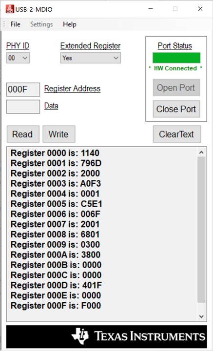
Which registers should I read on the EVM?

Reading register 0x0C00 gives 0x0140, which I decode as Fiber auto negotiation disable and forced speed 1000Mbit.

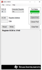
Any other registers I should read?

In addition, app note SNLA305 also specifies that register writes can be needed for 1000Base-X applications.

Please advise.

Regards

Lars

  • Further Register reads for additional info:

    These reads were performed without any copper or fiber connections to the EVM, only USB to power the board and for USB-to-MDIO access.

  • Hi Lars,

    Thank you for sharing the information. IEEE does not support force mode for1000Base-T, therefore we highly not recommend using force 1000Mbps mode.

    Based on your register read, it seems like the PHY is not link up at 1000Base-T copper mode. 

    If you want to work on only 1000base-T, we recommend to de-advertise 10Mbps and 100Mbps by writing register 0x0004 = 0001 and register 0x0009 = 0300.

    Enable the link partner auto-negotiation

    --

    Regards,

    Hillman Lin

  • Thank you for the response. Am I mistaken or does setting the straps for ANEGSEL_0 and for ANEGSEL_1 to 1 not do exactly what you propose, namely advertising 1000Mbit/s only on the copper side of the DP83869HM? Only advertising 1000Mbit should always give a 1000Mbit during auto negotiation (given the link partner supports 1000Mbit).

    During the design I can easily read and set register, but since I am aiming for a design without a controller I want to setup the DP83869HM in unmanaged mode using only straps. Is that possible?

    Please note that the register reads provided in the previous post was made on the EVM without copper and fiber connected, only USB for register read/writes.

  • Hi Lars,

    Just wondering are you looking for 1000Base-X (fiber) to 1000Base-T or SGMII interface to 1000Base-T/100Base-TX/10Base-T. Based on your strap earlier, it seems like you are configure in SGMII mode. If you want to configure in fiber mode, please follow the strap setting below:

    • OPMODE[2] = 1
    • OPMODE[1] = 0
    • OPMODE[0] = 0

    If possible, could you provide me a block diagram on your design?

    --

    Regards,

    Hillman Lin

  • My goal is 1000BASE-T to 1000BASE-X, i.e. 1Gbit media converter.

    My setup is as follows:

    The managed switch is setup to force 1000Mbit speed for the DP83869HM fiber Link Partner, i.e. no auto-negotiation on fiber side.

    I am not sure why you mention SGMII mode. The straps I mentioned in my earlier post is exactly what you say, namely OPMODE[2] = 1 and OPMODE[1] and OPMODE[0] = 0.

    With the test setup connected as shown above, I have taken a photo of the EVM.

    Here the straps are as follows:

    OPMODE[2] = shorted (i.e. MODE 1), OPMODE[1] = open (i.e. MODE 0), OPMODE[0] = open (i.e. MODE 0).

    LED_0: Pins 1 and 2 shorted = 1 (i.e. Fiber force mode)

    LED_1 and LED_2: Pins 1 and 2 shorted = 1 (i.e. Copper Auto Negotiation (1000 Advertised), Auto MDIX). This is according to Table 10 and 11 in SNLA318.

    MIRROR_EN = Closed (i.e. Copper : Mirror Enable) (I found this was necessary to get a link on the copper side).

    LINK_LOSS = Closed (i.e. Link Loss Pass Thru Disabled) (Testing with this strap showed no link loss on copper side when fiber connector was disconnected).

    LINK_LOSS = Open (i.e. Link Loss Pass Thru Enabled) (Testing with this strap showed link loss on copper side when fiber connector was disconnected).

    As you can see in the photo LED_0 and LED_1 are lit (constantly, not blinking), linkup is achieved on both copper and fiber side.

    I am able to ping the from one PC to the other in this setup, which seemingly solves my issue.

    However, I observe some unexpected register reads, that I would like you to comment on.

    I have performed register reads when strapped as mentioned above and indicated in the photo.

    When I change the LED_1 and LED_2 straps to connect pins 2 and 3 and remove LINK_LOSS jumper I get the following register reads:

    First of all, I do not understand why this strapping causes register 01DF to be 0x0004 and not 0x0044? The datasheet specifies 0x0044 to be the value for 1000Mbit media converter, but it seems only the three LSB's indicate the mode. Is 0x0004 OK?

    Second, why does strapping LINK_LOSS high change register 0x01EC to 0x1FF5? I would expect this register to change to 0x1FFC (toggling the LSB). Related to this, the the documentation specifies that register 0x01EC must be written the data 0x1FFC. Can this not be achieved via the dedicated strap?

    If this this due to an error, errata or anything else? I don't understand, so hopefully you will be able to shed some light on this.

    Regards

  • Hi Lars,

    register 0x01DF = 0004 should be fine for media converter mode for 1000Mbps

    Unfortunately, this is an errata. Link loss functionality could only tune by register setting.

    --

    Sincerely,

    Hillman Lin

  • According to my testing today I observed the following:

    With Link loss strap pulled down (jumper open on EVM) I disconnected the SFP module from the EVM. This caused both copper and fiber link LEDs on the EVM to turn off, the Ethernet switch indicated link down (fiber) and the Ethernet interface in the PC connected to the EVM also indicated link down, even with CAT6 cable still connected.

    With Link loss strap pulled high (jumper sshorted on EVM) I disconnected the SFP module from the EVM. This caused only fiber link LED on the EVM to turn off (copper link LED remained on), the Ethernet switch indicated link down (fiber) but the Ethernet interface in the PC connected to the EVM keat indicating link up, with CAT6 cable still connected.

    These observations indicate to me that the LINK_LOSS strap is controlling the link loss pass through feature of the DP83869HM. Is this correct? And if so, why must the 0x01EC register be changed?

  • Hi Lars,

    I will discuss with the team and provide you a response later.

    --

    Regards,

    Hillman Lin

  • Thank you Hillman

    For your information, the strap status register address 0x006E reads 0x380E when link loss is disabled and 0x180E when link loss is enabled.

    My testing shows this:

    Ping from PC connected to DP83869HM copper is pinging PC connected to switch. Pings are received OK.

    When link loss is disabled on the EVM, I observe link is retained on PC connected to copper when fiber is disconnected, pings obviously fail.

    When link loss is enabled on the EVM, I observe link is lost on PC connected to copper when fiber is disconnected, pings again obviously fail, but now the link loss is visible to the copper ethernet link partner of the DP83869HM.

    I have also read online that the DP83869HM exist in two silicon revisions. The register 0X003F is read as 0x0000 on my EVM.

    Please let me know if you need any further register reads or anything else.

    Regards

    Lars

  • Hi Lars,

    Sorry for asking multiple time. May I ask what is the main objective you are trying to achieve in the system? What kind of feature are you trying to look for? 

    For my understanding, you are able to see link up in the media converter mode (1000Mbps and 1000Base-X) when the link loss is disable. Is this not what you are looking for? 

    --
    Regards,

    Hillman Lin 

  • It’s fine, it is important to be sure.

    in my current setup, I have the functionality I am looking for. I am able to convert a 1000BASE-T interface to a 1000BASE-X and I can ping over the connection. Based on the link loss strap I am also able to either enable or disable LLPT. So the functionality is as I want. My main question is why the registers I read don’t match the expected values from the data sheet and app notes. In addition I don’t understand why the app note specifies a required register write to 0x01EC (toggle bit 0).

    My tests seems to show the desired result without the need for any register writes, but since that seems to go against the documentation of the IC, I am asking if I am overseeing anything or if I can omit the register write specified.

  • Hi Lars,

    Understood. I will discuss with the team on this.

    --

    Regards,

    Hillman Lin

  • Hi Lars,

    Thank you for the clarification.

    I confirm it with team. This configuration is not required on new revision of the DP83869 silicon.

    Reading register 0x0003 could tell you if the chip you are currently using in old revision or new revision. DP83869EVM should have the new revision on it.

    Thank you for your patience.

    --
    Regards,

    Hillman Lin

  • Thank you for the information. What is the expected data to be read from register 0x0003 for the old and new revisions?

  • Hi Lars,

    When you see register 0x0003 to a0f3, that should be the new revision.

    --

    Regards,

    Hillman Lin

  • OK. I read the register 0x003 earlier today on the EVM and it returned 0x0000. Is that the expected value for the old revision?

  • Hi Lars,

    Sorry for the confusion. It should be a0f3 for the new revision

    You shouldn't read 0x0000. It seems like something wrong on your MDIO access.

    --

    Regards,

    Hillman Lin

  • I can read other register just fine, as indicated in multiple of my previous posts. Is data 0x0000 expected for the old revision or should it read another value?

  • Hi Lars,

    Register 0x0003 = a0f1 is the older revision

    Register 0x0003 = a0f3 is the newer revision

    --

    Regards,

    Hillman Lin

  • Thank you.

    I have attempted to read the 0x0003 register again and after a power cycle I now read 0xA0F3.

    So everything seems to check out.

    I will close this thread as my intended design is now working on the EVM.

    Regards

    Lars