Tool/software:
I would like to confirm whether it is possible to use upstream power for downstream ports if I am using the TUSB4020BI solely for USB communication. Can the downstream ports be powered via VBUS in this configuration?
This thread has been locked.
If you have a related question, please click the "Ask a related question" button in the top right corner. The newly created question will be automatically linked to this question.
Tool/software:
I would like to confirm whether it is possible to use upstream power for downstream ports if I am using the TUSB4020BI solely for USB communication. Can the downstream ports be powered via VBUS in this configuration?
Hi Khosro:
You can use upstream Vbus as source for Vbus switch to control downstream port Vbus, don't recommend directly connect upstream Vbus to downstream port Vbus
Best
Brian
Hello Brian,
Thank you for the reply. Can I use this IC without programming for just simple low rate data application with defult registers or should I program this IC from USB upstream port?
Best regards,
Khosro
Hi Khosro::
You can just use the default setting for USB2 low data rate application.
Best
Brian
Hello Brian,
Would you please provide me layout files for the TUSB4020BPHP Evaluation Module?
Best regards,
Khosro
Hi Brian,
I just marked my unread notification, how can I accept friendship request?
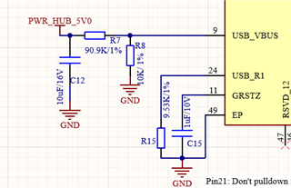
And is it possible to provide 3.3V regarding Pin.9 (USB_VBUS)? And in this case what is recommended value for R7 and R8?

Subject: Review Request for BUS_POWERED HUB Schematic
Hi Brian,
I have sent you the schematic for my BUS_POWERED HUB, which is designed for a simple low-speed application without a charging option. The main purpose of this hub is to transmit and receive low-speed signals.
Could you please review the schematic and provide feedback? I also have a few specific questions:
3.3V Supply from Pin 9 (USB_VBUS):
5V Supply after Rectifier Diodes:
Placement of FL1 (Connected to Pins 26 and 27):
Capacitor Optimization:
Thank you for your assistance in reviewing the schematic and addressing these questions.
Best regards,
And is it possible to provide 3.3V regarding Pin.9 (USB_VBUS)? And in this case what is recommended value for R7 and R8?
for 3.3v, divider can be 50k/10k. to get 0.5v on pin 9.
5V Supply after Rectifier Diodes:
- Is it acceptable to supply 5V to Pin 9 after the rectifier diodes?
pin 9 should be 0.5v
Placement of FL1 (Connected to Pins 26 and 27)
current location looks good.
Could you specify any unnecessary capacitors in the schematic to achieve a more optimal design?
I don't think 1nf caps are needed for 3.3v and 1.1v supply.
I'm working on review schematic and will be completed by tomorrow.
Best
brian
If I use the HUB controller with the default register, you mentioned that it supports low-speed data transfer. Do you mean 1.5 Mbps or 12 Mbps?
Hi Brian,
Thank you for reviewing my schematic, would you please send me the PCB? for sending the PCB, how can I accept your friendship request?
Sincerely,
Khosro
You are ok to send message , I say Hi to you with private message.
Best
Brian
Hello Brian,
I have tried to open .BRD file in Altium 24, but I could not unfortunately open it. If you have already cadence or similar softeare, could you please convert it and send it to me?
Best regards,
Khosro
Dear Brian,
I hope you're doing well.
Thank you for sending over the two sample files for the TUSB4041 EVM to help me with component placement on the PCB. However, I noticed that the file format is in .brd, which I am unable to open in Altium Designer 24.
Could you kindly convert the files to a .PCB format or another format that is compatible with Altium? It would be a great help for me to proceed with the design.
Apologies for any confusion, and thank you in advance for your assistance!
Hi Khosro:
I'm on business travel and will be back to office after 9/28. I will try to convert the files after I'm back to office.
Best
Brian