This thread has been locked.
If you have a related question, please click the "Ask a related question" button in the top right corner. The newly created question will be automatically linked to this question.
Tool/software:
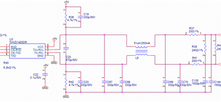
Hello, I saw a forum with the same name for this topic. I also encountered the same problem. The principle diagram is basically the same. The SN75176 used before will get better effect when replaced by THVD1420, but R will still have abnormalities. The pull-down resistance is 4.7k, the terminal resistance is 120Ω, and the current limiting resistance is 20Ω。
Is it necessary to adjust the pull-down resistance to achieve, how to adjust, thank you
Hi Shitong,
Do you have scopeshots of the issue you are seeing? Maybe probe the TXD, RXD, and the A and B pins (use a math function for A-B on the scope).
Is this also for a new design where you tried the SN75176B or is it an older design that used to work but now you're seeing issues?
Those 4.7k resistors are external fail safe resistors. You can size them to a lower value to get more noise immunity and get a better fail safe bias during idle conditions.
-Bobby
Sorry, I don't know how to explain, please search "SN75176B: N75176B: R pin received unexpected signal while the differentiated signal is 0(A-B) in noise environment. "I had the same problem he had here. It is currently intended to change 4.7k to 1k.
Yes, using stronger fail-safe resistors will increase the noise margin.
It would be helpful to capture the noise with an oscilloscope.
Clemen's is correct. Having the stronger fail safe resistors help with more noise immunity. My guess as to why the THVD1420 fixes your issue while SN75176B has an issue is because 176B's Vth+ is above GND while the THVD1420 has a Vth+ below GND (also known a internal fail safe bias protection) which is providing you some more margin when the system is idle.
Using an oscope may help you see the amount of noise your system has so it would still be helpful to capture that.
-Bobby