This thread has been locked.

If you have a related question, please click the "Ask a related question" button in the top right corner. The newly created question will be automatically linked to this question.

DS90C3201 Input Clarification

Other Parts Discussed in Thread: DS90C3201, DS90C387, DS90C387A, DS90C187, DS90C3202, DS90CR485, DS90C387R, HD3SS213, TFP401A

I'm comparing the DS90C3201 with the DS90C387/A parts and have some questions.

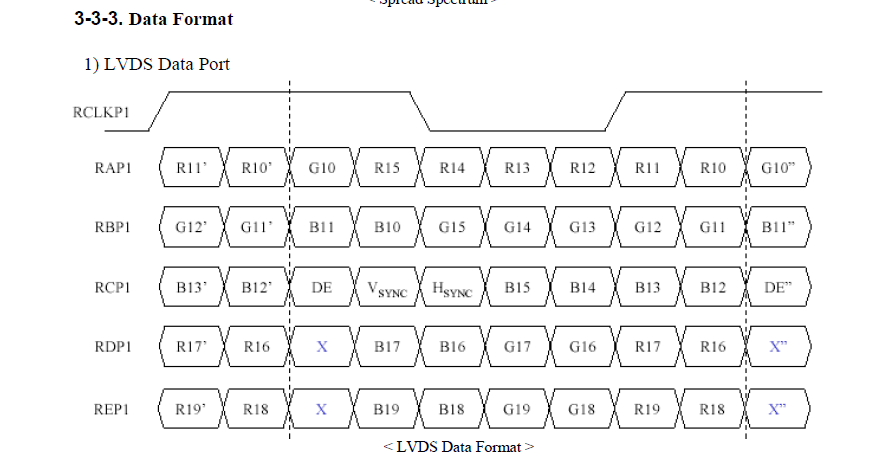
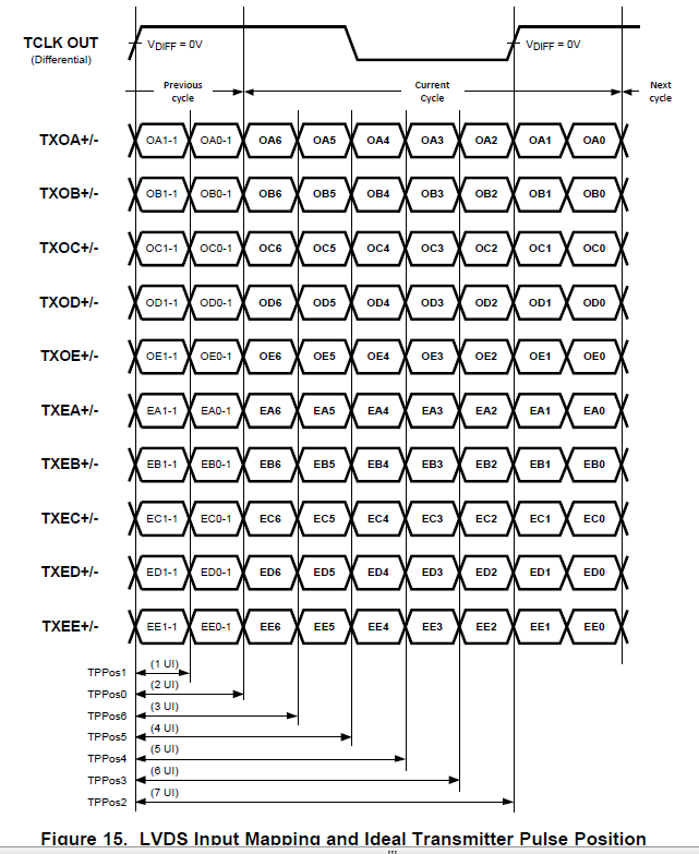
DS90C3201, 3.3V 8 MHz to 135 MHz Dual FPD-Link Transmitter, I’m confused why the inputs are in groups of 7, (i.e. TXOA [6:0]). The output is described as “LVDS 30-bit, 24-bit or 18-bit color data outputs” and it also says “The DS90C3201 transmitter serializes 2 channels of video data (10-bit each for RGB for each channel, totaling 60 bits) and control signals (HSYNC, VSYNC, DE and two user-defined signals) along with clock signal to 10 channels of LVDS signals and transmits them.”

How do you get 10-bit output when your input is only 7-bit? 7-bit is odd too because I've seen 6-bit (18-bit total) or 8-bit (24-bit) or even 10-bit or 12-bit. The nice thing about this part is that the output has 5 pairs of LVDS (TXOA-TXOE/TXEA-TXEE) which is needed when you want to drive 10-bit panels.

 DS90C387A, Dual Pixel LVDS Display Interface / FPD-Link, This seems OK but the input is limited to 8-bit per color so what do you do if your source is 36-bit? The input has a “dual channel” input so you've got a total of 48-bits but then it seems that you’re limited to a 24-bit output since you've only got a 4 pairs of LVDS.

The end goal is to be able to drive a few different LCD panels with different resolution and bit depth.

Thanks,

George

  • Hi George,


    I apologize for the delay in response. Somebody will be looking this for you and will reply shortly.


    Regards,

    Michael Peffers

    Analog Applications Engineer

  • Hi George,

    The LVDS serialization ratio of 7:1 is an industry standard format developed by National Semiconductor (now TI-SVA). The 30-bit support refers to the color depth of a pixel and is not related to the serialization ratio of the device. The 30-bit pixel color is broken up among 5 LVDS lanes which allows for the transmission of up to 35 bits. Some of these bits are used for the video control signals HS, VS and DE, while others are simply not used.

    The 2 channels mentioned in the datasheet refers to the groupings of even and odd pixel groupings of 5 LVDS data lines. This practice of separating even and odd pixels helps keep the speed of the LVDS lanes down, which simplifies the circuitry and saves power, while allowing for high resolutions. If you wish, you could also use these even and odd groupings to drive different displays, so long as the video data came from the same clock domain and used the same pixel clock frequency.

    As for the DS90C387A, please take another looks at the datasheet block diagrams. The device has 48 LVCMOS inputs for color and 8 LVDS outputs.

    Mike Wolfe

    DPS APPS / SVA

  • Hi Mike:

    Thanks for your reply. This 7:1 format and the color bit depth I guess is what is getting me confused. The HDMI receiver chip I'm using has "36-/30-bit Deep Color and 24-bit color support" and has several different output modes. I'd like to use their "36-bit SDR 4:4:4" which places each color bit on different pins (R[0-11], G[0-11], B[0-11]).

    If I look at a typical LVDS 10-bit Panel the bit mapping on the LVDS Channels is like this:

    Looking at the DS90C3201 bit mapping I see this:

    I guess I was stuck on thinking of the inputs as distinct color grouping and not that they could be generic inputs and what matters is how those inputs are serialized onto the LVDS channels?

    So if I have this understood now the actual "mapping would go like this:

    OA6 OA5 OA4 OA3 OA2 OA1 OA0
    G10 R15 R14 R13 R12 R11 R10
    OB6 OB5 OB4 OB3 OB2 OB1 OB0
    B11 B10 G15 G14 G13 G12 G11
    OC6 OC5 OC4 OC3 OC2 OC1 OC0
    DE Vsync Hsync B15 B14 B13 B12
    OD6 OD5 OD4 OD3 OD2 OD1 OD0
    X B17 B16 G17 G16 R17 R16
    OE6 OE5 OE4 OE3 OE2 OE1 OE0
    X B19 B18 G19 G18 R19 R18

    This makes sense for a single channel LVDS panel. Unfortunately the HDMI receiver I'm working with places the 
    Odd/even pixels on the same pin and uses the rising and failing edge of the clock to differentiate between the 2 signals. How would I use this part to connect to a dual channel 10-bit panel or can I?

    For the DS90C387 I meant to say that it would only support a dual channel panel with 4 lanes each and all of the 10-bit 1920x1080 panels I've seen require 5 lanes for each channel.

    Thanks,

    George

  • Hi George,

    If the HDMI receiver device that you are using outputs different pixels on rising or falling clock strobes, you need a device that support this double pump action(DDR) with a function to support a split out to a dual pixel interface or a very fast single pixel LVDS interface.

    If your intention is to receive HDMI video, convert to LVCMOS, then use DS09C3201 type device to convert to LVDS, I'm afraid we don't have a LVDS ser/des device that can support that color depth with a DDR interface. Although you could consider an FPGA or video processor to implement this type of functionality.

    We have several devices that support single pixel to dual pixel interfaces (DS90C187, DS90C387) or even a few devices with a DDR interface (DS90CR485, DS90C387R) but they all support a max of 24bit RGB (8bits per sub pixel). Currently, the only 30-bit RGB (10bits per sub pixel) LVDS ser/des device that we have is the DS90C3201/DS90C3202.

    Can you share the part number for the HDMI receiver device?

    Mike Wolfe

    DPS APPS / SVA

  • Hi Mike:

    Well that's the answer I've been afraid of getting for over the last month. I wanted to strip audio from the HDMI signal and TI doesn't have a part for this. I don't need to support HDCP and the only vendor that I found that sells a version of a HDMI receiver without HDCP is Analog Devices. I've been looking at their ADV7612 and if look at their Table 6 and Table 7 it shows the SDR and DDR formats that the part supports.

    It might be debateable that 10-bit support is truly needed but if the source has better than 8-bit why throw that resolution away?

    The 30-bit RGB on the DS90C3201 would be great if the ADV7612 didn't use DDR for "dual channel" (odd/even) but it looks like I'm stuck in a world of only half baked solutions. Going with a FPGA could work but then I believe the cost goes up considerably for a part that supports these bandwidths.

    Maybe I'm missing something so please let me know if you can think of a way for me to have my cake and eat it to!

    Thanks,

    George

  • Hi George,

    The debate about 8-bit and 10-bit per sub pixel is quite interesting. For human displays it is easy to argue that 8-bits per sub pixel (also called 24-bit RGB or True color) is plenty for the human eye, while perhaps machine vision/imaging can make better use of the 10-bit (30-bit RGB or Deep Color) or higher color depths.

    There are techniques out there that help to convert higher color depths to lower color depths more smoothly. One of the most common techniques is called dithering.

    If you do end up selecting a video imaging processor or FPGA, you can investigate using dithering to better convert your 10bit per sub pixel data to 8 bit per sub pixel data.

    The alternative would be to simply chop the LSB off of each channel. This would take your color space from over 1 billion colors( (2^10)^3 for 10 bits per sub pixel) to about 16 million colors ( (2^8)^3 for 8 bits per sub pixel). With this type of approach it would be very difficult to observe any color loss even if you used a magnifying glass on your display.

    I don't have access to the full datasheet for your HDMI receiver, but be sure to pay close attention to the output data format of that device versus the input data format for the DS90C387R. If they mesh then you might have a good solution.

    Mike Wolfe

    DPS APPS / SVA

  • Hi Mike:

    I've been down that road debating bit depth not only for images but for audio as well. I didn't want to spend the time but I may have to go abck and review FPGA solutions and see what they can do without spending a fortune.

    I guess what gets me is that HDMI has supported 36-bit color for years and there are plenty of LCD panels that support 10-bit inputs yet TI has seemingly done nothing with this product line in years. Without divulging secrets or stepping on any marketing toes do you know if there's any plans to expand this product line or will it die off like the National name (or Burr Brown)?

    I really would like to differentiate our product from others on the market and using a 10-bit panel with 10-bit inputs would do that.

    Thanks,

    George

  • Hi George,

    If you take a look at the other video interfaces it is easy to see why supporting larger color depths in LVDS is not very popular. if you support 6 bits per color then you require 3 LVDS data + 1 LVDS clock. If you do 8 bits per color, then you will need 4 LVDS data + 1 LVDS clock. For 10-bits per color you now need 5 LVDS data + 1 LVDS clock. And then if you require a high resolution and need to support dual pixel 10 bit per color, then your total lane count becomes 10 LVDS data + 2 LVDS clock. For this case that means you require 24 conductor traces across your cables and connectors. Maintaining the clock to data skew across such a wide bus can be very challenging for system designers.

    There are newer video interface technologies that can support higher resolutions and/or higher color depths with fewer serial lanes than LVDS. For example, MIPI, HDMI, or Display Port are all newer interface standards that have advantages of LVDS.

    There is a good article on the TI website comparing various video interface technologies, that I recommend read:

    http://e2e.ti.com/support/interface/high_speed_interface/m/videos__files/227084/download.aspx

    Since you originally mentioned you wished to drive multiple panels, if you went the Display Port route you could use something like the HD3SS213 which is a 2:1 or 1:2 mux to replicate your video stream. This video interace also allows you to support a variety of color depths and resolutions.

    Mike Wolfe

    DPS APPS / SVA

  • Hi Mike:

    If you look at the market for "raw" LCD panels you'll find that >90% use LVDS interface. The only panels that I'm aware of that use a Display Port interface are for Apple but if I could find some good screens with Display Port interface your idea is a good one.

    10-bit panels are definitely not common but who wants to be ordinary?! I've looked at a few large panel datasheets (42") and they also used LVDS.

    I'll take a look at that article and see if it helps shed some light on this.

    George

  • Hi George,

    I think it depends on the market you are looking at. The latest generation of medium sized panels for portable applications prefer a more compact interface such as MIPI or embedded Display Port (eDP). Smaller panels for portable applications might use MIPI, FlatLInk/3G, MPL2 or some other very compact lower power interface for low to medium resolution displays. When it comes  to large commercial displays you still see quad LVDS, but the trend is to move towards a higher throughput interface like eDP. Think of how many LVDS links you would need to support a 2k or even 4k display! And then you have to factor in your refresh rate. That could really bump up your LVDS lane count.

    So far you have been focused on the difference between true color versus deep color for your user experience. I would also suggest that you consider the refresh/frame rate of your display. The refresh rate of your chosen display can easily have a more dramatic impact on user experience than deep/true color.

    Mike Wolfe

    DPS APPS / SVA

  • Hi Mike:

    I totally agree with you on the portable market and the usage of MIPI or eDP but unfortunately that's not our target. We're in the ~15"-23" range and from what I've seen it's still 99% LVDS yet I'm left scratching my head at the severely limited solutions to go from TMDS to LVDS, especially considering almost all of the monitors/TVs in this range accept a HDMI input.

    I agree on the color depth vs refresh rate but I'm on the assumption that my signal is going to be FHD@59.9Hz.

    What about exploring the DDR signal and trying to extract that into something the DS90C3201 can handle, would any of the SERDES parts be able to do that?

    George

  • Hi Mike:

    I was doing some additional research on Display Port and correct me if I'm wrong but I don't see a solution from TI that converts TMDS to DP, I only see DP to TMDS.

    I really don't see anything on the TMDS receive side of the chain except for the ancient TFP40x/50x series of parts that came from the National acquisition.

    Hopefully I just am missing some hidden parts...

    George

  • Hi George,

    Unfortunately those types of devices are supported by a group in Dallas. I am part of the Silicon Valley Analog group (formerly National Semiconductor). The TFP series of devices is also supported by the Dallas team and was not part of the National portfolio.

    Maybe we can get someone from the ICP team to respond here.

    Mike Wolfe

    DPS APPS / SVA

  • Hi Mike:

    OK, I really would appreciate it if you could ping someone there. I seriously have been trying to get answers to these questions since November and this project is dead until I come up with a solution.

    Thanks,

    George

  • Hello George,

    Can you re-elaborate what are your needs here?

    Regards.

  • Attached please find a quick block diagram I sent into sales back on November 15, 2013. The design needs to be flexible as it will be used on different projects. The problem with this proposal is that the DS90C387 is limited to 8-bit LVDS LCD panels. The DS90C3201 provide 10-bit dual channel LVDS but the "DDR" output of the ADV7612 latches odd/even pixels on the rising/falling edge of the clock and the DS90C3201 expects odd/even to be input on different pins.

    I show the TFP401A in the block diagram but using that part does not allow me to strip out the audio packets and feed the I2S output to external audio DAC.

    I don't really want to but the latest idea is to perhaps find something that will convert the ADV7612 DDR output into separate odd/even pins that the DS90C3201 requires.

    The DS90C387 is nice because I can go from single channel input to dual channel output or single channel output but I am limited to 8-bit RGB and one of out applications is going to be displaying high resolution photos so "full" color depth is preferred.

    The panels I am looking at have 10-bit RGB and 1920x1080 resolution which require 5 LVDS pairs (plus clock and control) which I don't believe can be successfully connected to the DS90C387

    Regards,

    George

    HDMI to LVDS Proposal.pdf
  • Hi Elias:

    Been a few days so I thought I'd ping you to see if you've had a chance to review this.

    Thanks,

    George