This thread has been locked.

If you have a related question, please click the "Ask a related question" button in the top right corner. The newly created question will be automatically linked to this question.

MAX202 and micro UART interface signal overshoot issue

Other Parts Discussed in Thread: MAX202

Hi,

Can anyone help to resolve below issue.

We have seen the following issue in HPAC04 RS232 circuit using MAX202.

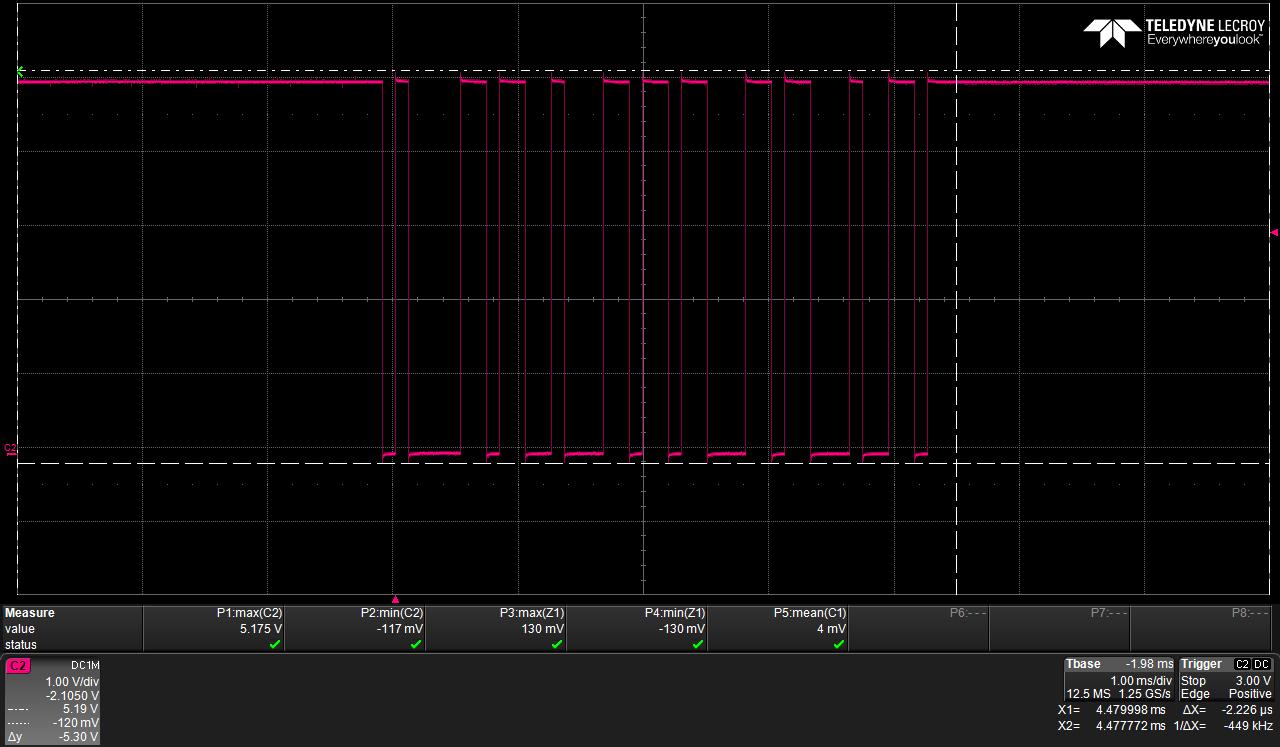
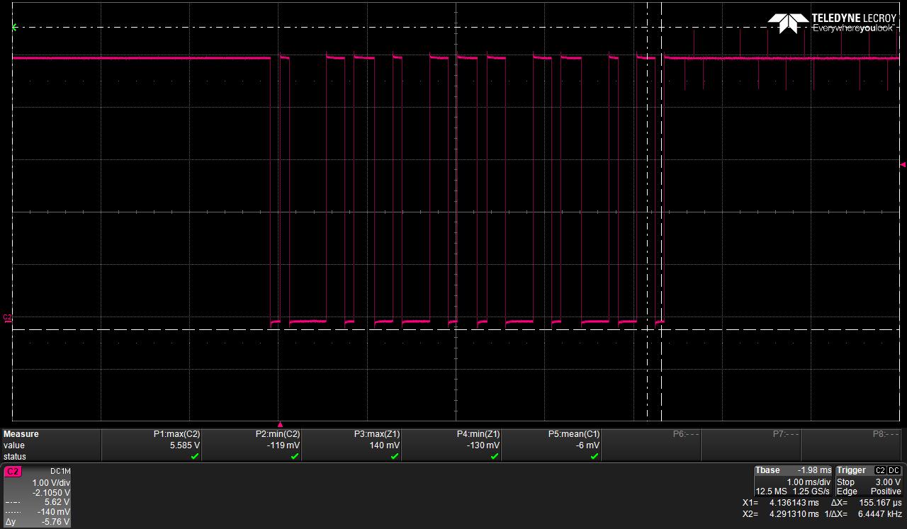
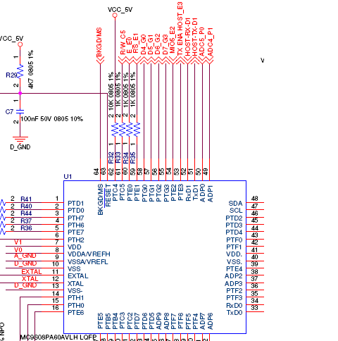
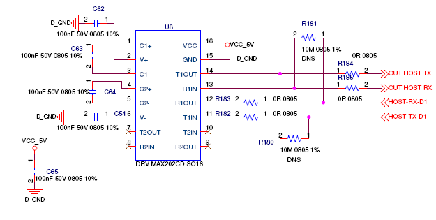
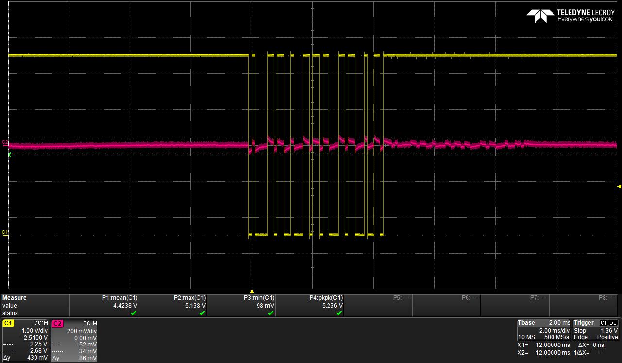
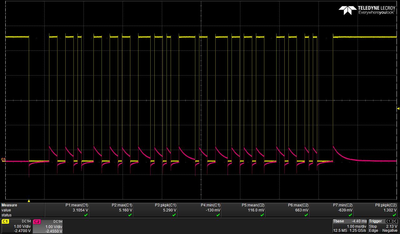
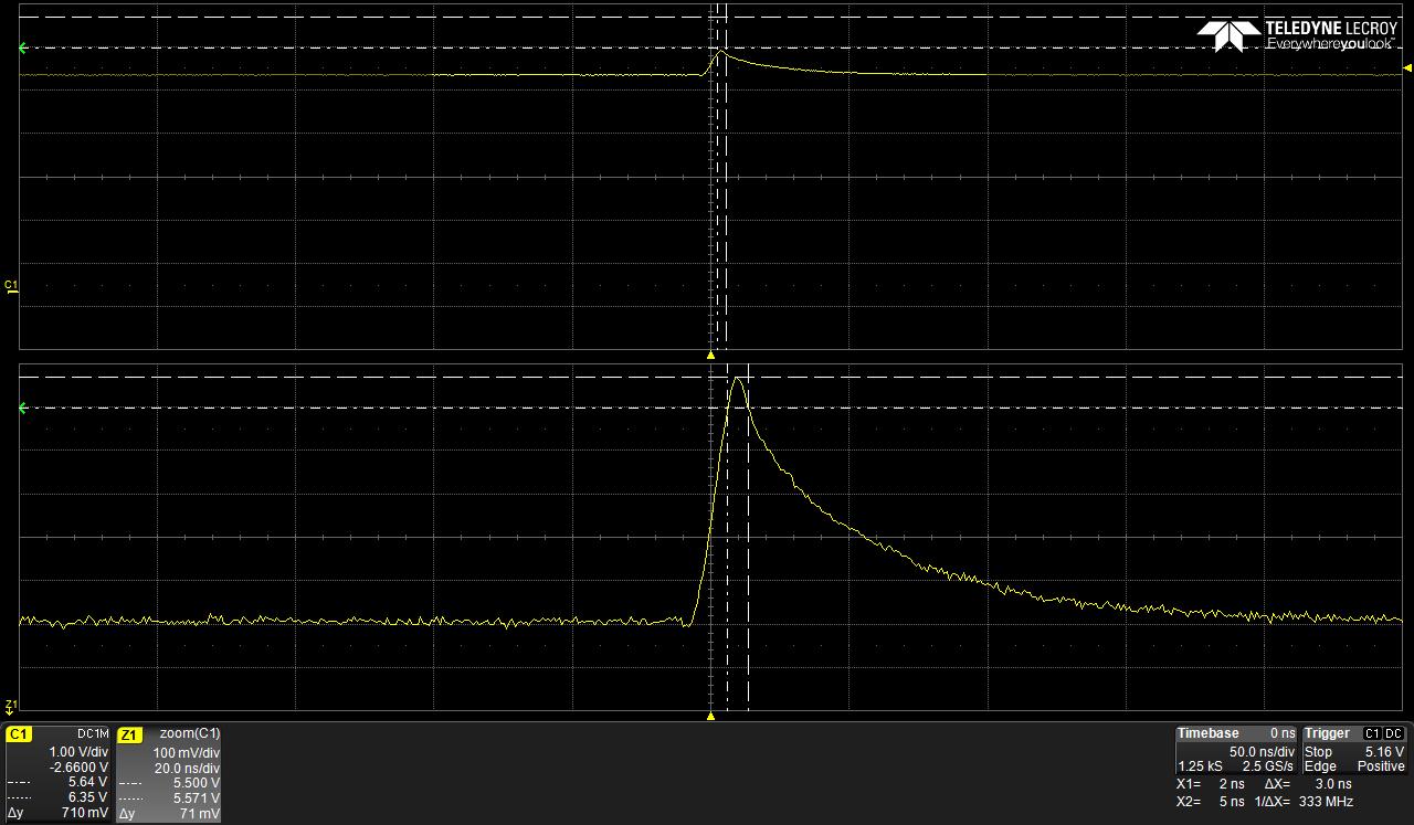
The RX & TX from microcontroller(MC9S08PA60) to the MAX202 has overshoots at the transitions of these digital signals. Also there are spikes on RX line when TX is being transmitted and vice versa. These overshoots are exceeding the limits of the ICs(5.5V). The circuit is designed as recommended in the datasheets.

Attached schematics and  waveforms for your reference.

Rgds,

Umamahesh

  • Umamahesh,


      Are these transients also present on the VCC line or ground?

  • Hi Ron,

    Thanks for your Reply.

    No. The transients are not present on the Vcc or ground. They occur only at the transitions of the Rx/Tx from low to high or high to low.

    Rgds,

    Umamahesh,

  • Umamahesh,I did some testing on the MAX202 today.
    I saw up to 100mV peak on ROUT1 (pin12) from input on DOUT1 (pin11).
    I saw up to 40mV peak DIN (pin11) from input on RIN1 (pin13)
    I suspect this coupling is PCB trace to trace capacitive coupling.
    How long are the circuit board traces from UART to MAX202?
    Do the lines from MAX202 pins 11 and 12 run close to each other?
    If the pulses are in the low nano-seconds then they shouldn’t be a problem unless they were much bigger.
  • Hi Ronald,

    The two signals are routed in parallel and run close to each other. The length of the Rx & Tx traces is 47mm & 55mm respectively.

    By pulses you mean the overshoots right? They are in few hundreds of nanoseconds range. 

    Rgds,

    Umamahesh

  • Umamahesh,

    If R182 is close to MAX202 it could be removed for a test. If ASIC sends HOST-TX-D1 data (that won't get to MAX202) and there is still signal on HOST-RX-D1 line then the circuit board is the reason.
  • Hi Michallick,

    Thanks for the support. We have performed the suggested tests.

    It is observed that the Rx lines contain the signal even when the resistor R182 is removed – waveform 232rxtx20. Similarly when the resistor R183 is removed if the micro receives data on R1OUT there is signal on Tx at the MAX202 IC pin – waveform 232rxtx5.

    As for the peak pulse levels I mentioned earlier it is in the hundred nanoseconds range. This was the duration of the entire charge and discharge of the pulse. To be precise the voltage exceeded the limits(5.5V) only for 3ns(waveform 232rxtx21).

    The voltage peak levels at the IC were found to be 5.57V with 0Ohms at R182,R183. After changing the series resistors at the IC to 1kOhms this peak reduced to 5.13V at MAX202 pins. Though at the micro pins the peak is 5.57V for 3ns. We will check the micro specifications to make sure if this is within tolerable limits.

  • Umamahesh,

    Thank you for the wave forms and testing. The 3nS peak voltage 5.13V or even 5.57V is acceptable for MAX202.