This thread has been locked.

If you have a related question, please click the "Ask a related question" button in the top right corner. The newly created question will be automatically linked to this question.

Problem with the TUSB8040A1.

Other Parts Discussed in Thread: TUSB8040A1

Dear all, I have a problem with the TUSB8040A1: The "+5V" power supply is not directed  to all downstream USB connectors, although the H/W settings of the chip seems to be OK. Specifically:

All the PWRONxZ_BATENx signals have external pull-up resistors (4K7). In this way, during power-up (reset) the chip "sees" HIGH on these pins, enabling the power for all the USB downstream ports. So, after that (i.e. in normal operation) the chip is supposed to provide LOW on all these signals. (These signals control some external switches which -in turn- let the "+5V" pass to the USB connectors.) However, we don't get LOW on all these signals but just in some of them, in a rather random way for the several cards. (E.g. on  one card we get LOW on 2 of these signals, on another card we get LOW on one of these signals e.t.c.) The most weird thing is that this behavior remains exactly the same, even if I change the settings for these signals. I.e. if I remove the pull-up resistors (or even if I mount pull-down resistors) which means that the chip 'sees" LOW on these pins (at the begining) and it should disable all the external switches (in normal operation) the whole situation remains the same (i.e. some ports have "+5V" and some others don't ).

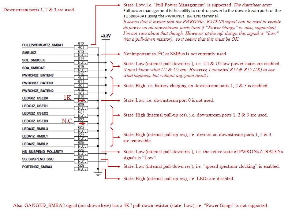
All the other H/W settings seems to be, also, OK. However, I present you all my valid settings:

FULLPWRMGMTZ_SMBA1 is LOW (through external 4K7 pull-down res). This enables the power management as mentioned previously. (If this signal is setted HIGH, no "+5V" passes to any of the USB ports.)

SCL_SMBCLK & SDA_SMBDAT are LOW (through internal pull-down res), hence U1 & U2 low power states are enabled. (I'm not sure what U1 & U2 staes are. However, I mounted external pull-up res on these signal to see what happens, but nothing changed anyway, so it seems that these signals are not important.)

All LEDGxZ_USEDx are HIGH (through internal pull-up res), so all downstream are used.

All LEDAxZ_RMBLx are HIGH (through internal pull-up res), so devices on all ports are removable.

HS_SUSPEND_POLARITY is LOW (through internal pull-down res), so the active state of the PWRONxZ_BATENx signals is "low".

SS_SUSPEND_SSC is LOW (through internal pull-down res), so the "spread spectrum clocking" is enabled.

PORTINDZ_SMBA3 is HIGH (through internal pull-up res), so LEDs are disabled.

GANGED_SMBA2 is LOW (through external 4K7 pull-down res), so "power gangs" is not supported. (I, also, tried a 4K7 pull-up res on this pin but nothing changed on the overall behavior.)

So, I need some help on that. FYI, I also disconnected the "control pin" of the external "power switch" from the corresponding "faulty" PWRONxZ_BATENx signal (to see if the "power switch" may cause the problem), but, also, the sityation remains the same.

Thank you in advance.

George 

  • Hi George,

    The PWRONxZ_BATENx signals are sampled high or low at POR to determine if battery charging is enabled on that port.  If the port has an external pullup installed, then battery charging is enabled.  After power on reset, whenever there is no upstream connection on the hub and USB_VBUS is low, battery charging is enabled on the downstream ports if PWRONxZ_BATENx has an external pullup (downstream port power is on).  Whenever there is no upstream connection on the hub and USB_VBUS is low, battery charging is not enabled on the downstream ports if PWRONxZ_BATENx has no external pullup (downstream port power is off).

    Whenever there is an upstream connection on the hub and USB_VBUS is high, the setting of PWRONxZ_BATENx (downstream port power is on or off) is determined by the USB host.  Typically all ports are powered on after enumeration.

    If you are seeing unexplained port to port variation, there may be an assembly issue or insufficient solder on the thermal pad.

    Regards,

    JMMN

  • Hi JMMN. Thank you for your reply. Let me see if I understood well:

    1) If the PWRONxZ_BTENx signals have pull-up res (i.e. HIGH during POR), then the "battery charging" function is enabled. This means that if the Host is not connected to the TUSB's upsteam port (i.e. USB_VBUS is "low") then the "+5V" still remains on the USB downstream connectors in order to charge the batery of the several devices (which are connected on these connectors).

    2) If the the Host is connected to the TUSB's upsteam port (i.e. USB_VBUS is "high") the "+5V" should be present on all USB downstream connectors by default (i.e. it doesn't matter what the state of PWRONxZ_BTENx signals is, during POR).

    Am I right about all the above??? Please, confirm that I understood well.

    If so, then I really shouldn't care about the setting of the PWRONxZ_BTENx signals (in fact, I really don't care to charge any batteries). I suppose that -after POR, i.e. in normal operation- and as long as the upstream port is connected to the Host, I should see LOW on all PWRONxZ_BTENx signals (and all the external "power switches" should be activated, providing "+5V" to all USB connectors). But, unfortunately, this doesn't happen.

    I, also, tried a larger value for the POR capacitor (1uF) but without any good results (even with 10uF the situation remains the same).

    I'll also take into consideration the "bad soldering issues" that you mentioned. However, this is ulikely to happen. As I've already said, the only way to control the external "power switch" effectively is to disconnect its "enable pin" from the corresponding "faulty" PWRONxZ_BTENx signal and pull it down to gnd (i.e. giving a "low" state and forcing the "power switch" to be "closed"). In this way, I get the "+5V" on the USB connector. Moreover, I still see a "high" state on this disconnected PWRONxZ_BTENx signal, even if I mount a pull-down res on this signal. This proves that the pin is well-soldered and the chip itself provides this "high" state (otherwise it should be "low" due to the pull-down res). And I don't know why this happens. Note that, always, the same port on a card has this problem. But the "faulty" ports on the several cards are different. (E.g. on one card the "faulty" port is the #3 while on another card the "faulty" ports are the #1 & #3 e.t.c.). And the weird thing is that all the settings (presented on my initial post) are the same on all cards.

  • 1) If the PWRONxZ_BTENx signals have pull-up res (i.e. HIGH during POR), then the "battery charging" function is enabled. This means that if the Host is not connected to the TUSB's upsteam port (i.e. USB_VBUS is "low") then the "+5V" still remains on the USB downstream connectors in order to charge the batery of the several devices (which are connected on these connectors).

    [JMMN] Yes.

    2) If the the Host is connected to the TUSB's upsteam port (i.e. USB_VBUS is "high") the "+5V" should be present on all USB downstream connectors by default (i.e. it doesn't matter what the state of PWRONxZ_BTENx signals is, during POR).

    [JMMN] Yes, once the host has finished configuring the hub.  +5V will not be on the downstream port  if the hub is in programming mode or a port has an overcurrent event.

    If so, then I really shouldn't care about the setting of the PWRONxZ_BTENx signals (in fact, I really don't care to charge any batteries). I suppose that -after POR, i.e. in normal operation- and as long as the upstream port is connected to the Host, I should see LOW on all PWRONxZ_BTENx signals (and all the external "power switches" should be activated, providing "+5V" to all USB connectors). But, unfortunately, this doesn't happen.

    [JMMN] Yes, the TUSB8040A1 will overdrive the pullup or pulldown.  Can you provide a schematic (partial is fine).  And can you install the usbview.exe utility from Microsoft and see how the how  is reporting itself?  It sounds like the hub may have a configuration issue. 

  • Hi, JMMN. Thank you very much for your clarifications. Our set-up is as follow:

    [ PC ] ----------------- [ (US port) Hub#1 (DS port) ] ----------------------- [ (US port) Hub#2 (DS ports X3) ] ---------------------------Devices

    The two hubs are not the same (i.e. Hub#1 and Hub#2 are two different designs, however they are both based on the TUSB8040A1).

    The problem is on the Hub#2 with the 3 downstream ports. And the problem is that we don't get "+5V" on all ports. As I said, the most weird thing is that the settings of all samples (for Hub#2) are exactly the same, but we get "+5V" on different ports for every sample in a random way. (Of course, the port which has the "+5V" is OK, i.e. the device which is connected to that port communicates with the PC, exchanging data nicely.)

    Another issue that I have observed is that the Hub#2 is much hotter than the Hub#1. So, I had to mount a small heat-sink on the chip in order to be able to operate in a long term (otherwise the card stoped its operation after a few minutes). I don't know why this happens and I wonder if this issue has to do with the specific problem that we face. I, also, wonder, if a kind of latch-up takes place on the chip which leads to all these aforementioned problems. If so, then maybe it has to do with the "power supplies sequence" (although I think that this is unlikely to happen because I followed the ref. design and I used the exact regulators mentioned in this ref. design). What do you think about that???

    Here is what we get from the usbview.exe tool concerning the Hub#2 (for this sample, only one downstream port operates well and one device is connected to that port):

    External Hub: USB#VID_0451&PID_8046#9&2721f6f2&0&1#{f18a0e88-c30c-11d0-8815-00a0c906bed8}
    Hub Power:               Self Power
    Number of Ports:         3
    Power switching:         Individual
    Compound device:         No
    Over-current Protection: Individual

    Device Descriptor:
    bcdUSB:             0x0300
    bDeviceClass:         0x09
    bDeviceSubClass:      0x00
    bDeviceProtocol:      0x03
    bMaxPacketSize0:      0x09 (9)
    idVendor:           0x0451 (Texas Instruments)
    idProduct:          0x8046
    bcdDevice:          0x0100
    iManufacturer:        0x00
    iProduct:             0x00
    iSerialNumber:        0x00
    bNumConfigurations:   0x01

    ConnectionStatus: DeviceConnected
    Current Config Value: 0x01
    Device Bus Speed:     Unknown
    Device Address:       0x03
    Open Pipes:              1

    Endpoint Descriptor:
    bEndpointAddress:     0x81  IN
    Transfer Type:   Interrupt
    wMaxPacketSize:     0x0002 (2)
    bInterval:            0x08

    Configuration Descriptor:
    wTotalLength:       0x001F
    bNumInterfaces:       0x01
    bConfigurationValue:  0x01
    iConfiguration:       0x00
    bmAttributes:         0xE0 (Bus Powered Self Powered Remote Wakeup)
    MaxPower:             0x00 (0 Ma)

    Interface Descriptor:
    bInterfaceNumber:     0x00
    bAlternateSetting:    0x00
    bNumEndpoints:        0x01
    bInterfaceClass:      0x09 (Hub)
    bInterfaceSubClass:   0x00
    bInterfaceProtocol:   0x00
    iInterface:           0x00

    Endpoint Descriptor:
    bEndpointAddress:     0x81  IN
    Transfer Type:   Interrupt
    wMaxPacketSize:     0x0002 (2)
    bInterval:            0x08

    Unknown Descriptor:
    bDescriptorType:      0x30
    bLength:              0x06
    06 30 00 00 02 00

    Please, take a look on this text report and verify that everything is OK.

    Also, the PC recognizes the Hub#1 and Hub#2 (and the device(s) connected on Hub#2).

    I look forward for your further reply. Thank you very much so far.

  • Hi George,


    Can you confirm that you are marking the ports used or unused using the external pullups / pulldowns? Do you set any ports as non-removable?  There is an erratum with port numbering when both non-removable and unused ports are set up on the same TUSB8040A1 hub. 

    Do you only see problems on Hub#2?  Or do you see them on Hub#1 as well? 

    I'm concerned about the thermal pad connection on Hub #2.  The hub should not get that hot.  I have run the EVM with USB 3.0 and USB 2.0 traffic simultaneously on all four downstream ports for hours and the hub gets hot, but it never stops operating.  How many vias are in the pad?  What's the copper weight of the board?

    Thanks

    JMMN

  • Thank you for your quick reply, JMMN. I' ve presented my settings on my initial post. However, I send the part of the schematic (Hub#2) concerning the settings (see below).

    As you see, 1,2 and 3 ports are used. Due to the chip's internal pull-up resistors, the state of the LEDGxZ_USEDx and LEDAxZ_RMBLx (x=1, 2, 3) is "high", which means that ports 1, 2 and 3 are used and all the devices are removable. There are no external settings for the port 0, as this port is not used. However, even for this port all these aforementioned signals must be, also, "high" due to the chip's internal pull-up resistors. So, the erratum (that you refer to) must not occur.

    About the excessive heat observed on the chip of Hub#2: The weird thing is that the thermal pad for both Hub#1 and Hub#2 are the same and the same rules were followed for the design. Essentially, this specific part of the PCB is the same for both Hubs. Furthermore, the same traffic passes through the TUSB chips of both Hubs (Camera ---> Hub#2 ---> Hub#1 ---> PC), so it is supposed that these chips should be heated on the same rate.

    I still believe that something "is wrong" about the internal operation of the chip (Hub#2) (although we get traffic data on the operating ports) which leads to the specific problem that we face (no "+5V" on all ports) and, also, leads to the over-heating of the chip. I have the sense that if we succeed to overcome this problem, we will get a "normal heat" on the chip (as on Hub#1). So, as a first step, we have to solve this problem (and then we can see if the over-heating remains). 

  • Hi again. Concerning the schematic for the chip's settings (see my previous post) the "N.C." means "not mounted". It is supposed that there are internal pull-up or pull-down resistors inside the chip. Indeed, the LEDG1Z_USED1, LEDG2Z_USED2, LEDG3Z_USED3, LEDA1Z_RMBL1, LEDA2Z_RMBL2 and LEDA3Z_RMBL3 are all "high" (+3,3V), due to the chip's internal pull-up resistors.

    Btw, here is what we did for the thermal pad:

    16 vias (i.e. we use the same number of vias as recommended in the datasheet).

    Hole diameter (of each via)=0,4mm (i.e. we use even larger vias than recommended in the datasheet).

    All these vias are connected to the gnd plane which lies in an internal copper layer. This gnd plane extends to the full size of the card and its dimensions are: 80,772mm X 83,82mm (or 3,18 X 3,3 inches) (hence, its surface is somewhat less than 67,7cm2) and copper thickness=18um.

    Thermal pad (copper) thickness=38um

    Did you check the schematic of the chip's settings??? Can you verify that everything is OK??? Do you have any other suggestions???

    If you verify that nothing is wrong concerning the settings, then maybe I could send you the whole schematic to take a look. However, this must be confidential and I can't publish it in an "open" forum like this. If so, then let me know your e-mail address so I can send you the schematics.

    We would appreciate some more help by you. Otherwise, we'll have to quit this specific design and make another one using another Hub controler chip (which means a lot of effort, money and time loss for us.)

  • Hi JMMN. I have two questions:

    1) Is it possible that the chip operates well (at least for some of its ports, as in my case) although it may has not been configured by the PC???

    2) What does exactly mean that "a device on a port is removable"??? How does the chip behave in such a case???

    Please, answer to these questions. Your answers may help me to overcome the specific problem.

    Best regards

    George

  • Hi George,

    Marking a port as non-removable (device or hub permanently connected) does not change the functional operation of the hub at all, it is only done for compliance reasons. My only concern here was that the TUSB8040A1 had an issue where if some ports were marked non-removable and some ports were marked unused, the port numbering on the USB 3.0 side of the hub and the USB 2.0 side of the hub did not match. If this was the case, I would still expect all your devices to behave the same way.

    Can you send the screenshot of usbview? I would be interested to see if it reports all the downstream ports on the 2nd tier hub or if it thinks only one or two ports exist? I'll send you a direct email address so you can send your schematic.

    Thanks!
    JMMN
  • Hi JMMN. Here are the screenshots:

    1) When no Hub is connected:

    [The 4 ports of the Root Hub (PC) are not connected.]

    2) When only the 1st Hub is connected:

    [Under the Root Hub there is another USB3.0 Hub with just one DS port which is not connected. (Also, the USB2.0 part of this Hub appears as a separated connection.) The other ports of the Root Hub are not connected. (However, for the Root Hub, 3 more "not connected" ports should be shown instead of 2. This must be a kind of bug of this tool.]

    3) When the 2nd Hub is also connected (this is the most important screenshot):

    [Now, under the 1st Hub, you see another Hub (the 2nd one) with its 3 used ports "not connected" (as no device has been connected on this Hub). Hence, the PC recognizes all the 3 ports of the 2nd Hub.]

    In my previous posts, I had asked two mote questions (not answered yet):

    1) I wonder if (for some reason) the proper configuration of the chip (by the PC) has been failed. In such a case, is it possible that the chip still operates well (at least for some ports, as in my case)??? (Or, in other words, if the configuration was failed, then should all ports be "dead"???)

    2) Have you checked the settings of the chip (that I've sent you in a previous post)??? Can you verify that they are OK???

    If there are no further suggestions by you, then you should send me your e-mail address in order to be able to send you the full schematic.

    Thank you very much for your help till now.

    Best regards

    George

  • Hi George,

    I sent you a direct email earlier today with my address. Please send a schematic.

    The system configuration looks correct. If the host does not enumerate the hub, I would not expect any of the ports to work.

    Thanks,
    JMMN
  • Hi JMMN. I have not received any e-mail from you (I can't find it neither in the "inbox" nor in the "junk mail"). Please, send it again and I'll send the schematic to you asap.

    Thank you very much.

    George

  • That's OK. I found your e-mail. I'll send you the schematics.
    Thanks again.

    George
  • Hi JMMN. I have sent you the schematics on your e-mail.
    I look forward for your reply.
    Thank you in adcance.

    Best regards

    George