A related question is a question created from another question. When the related question is created, it will be automatically linked to the original question.
If you have a related question, please click the "Ask a related question" button in the top right corner. The newly created question will be automatically linked to this question.
That's an interesting question. I think if you wanted something that were truly RS-422 compatible at all of the interfaces, the best approach would be the obvious one of using two RS-422 receivers, an OR gate (or equivalent circuit using diodes, etc.), and an RS-422 transmitter.
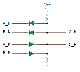
If there is a lot of margin in the application (i.e., if the distances are short and the signal swing is really 0 V to +5 V as shown in the attachment) and you do not need full standards compliance, then you may be able to get a passive circuit to work. Here is one idea:
This should give a high-level output on C if either A or B are sending a logic high and a low-level output otherwise. It is non-ideal, though, since the diodes will cause some drop in voltage and it is not possible to properly terminate the output. The pull-up and pull-down resistors would need to be much weaker than a typical termination resistance, so if terminated the low-level differential voltage would be closer to 0 V than the desired -5 V.
I would add termination Resistance for A and B just before the diodes
I would turn off any termination at C (system 2)
I would make the wires from box to C (system 2) as short as possible.
First thanks.
second, can you recommend actual values of resistors and diodes ?
Do I need the GND line from system 1 and connect it to GND line of system 2.
Can you Ron or Max test it or analyze it in ANALOG simulation software to get more data for success at first time.
I need also to combine/merge x4 RS422 lines into x1 RS422 line.
Those lines would transmit data log, gyro, echo sounder through RS422.
I'm trying to find out if I can apply the solutions above, or if it is something completly different, or if it is even possible?
Thank you for any tips.
Yes, the circuit that Ron shows above could be extended to any number of RS-422 channels. This provides a "wired-OR" function so that a high level on any of the input buses (marked A and B) will translate to a high level on the output bus (C).
Thank you for the kind answer. Now I fully understand the principle of the solution above.
Now I have something that bugs me, protocol wise. If all my 4 RS422 lines are transmitting packets/frames simultaneously, the data would be mixed and unusable. How can I combine the incoming packets/frames one after the others? Shouldn't I put some buffers?
I'm a bit lost.
Yes, you are right, a solution like this at the "analog" (physical layer/transceiver) level would not be able to handle more complex functions like buffering frames. You would need a more intelligent device (with memory) like a microcontroller if you needed to store frames and forward them out at a later time.
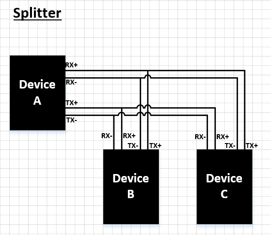
Actually, I need to do an RS422 splitter (1 to 2) and RS422 combiner (2 to 1). So there would be 3 devices in the network. I can't figure out how to connect all together.
- Splitter: I need to split a signal from device A to device B&C, which is easy considering it is RS422.
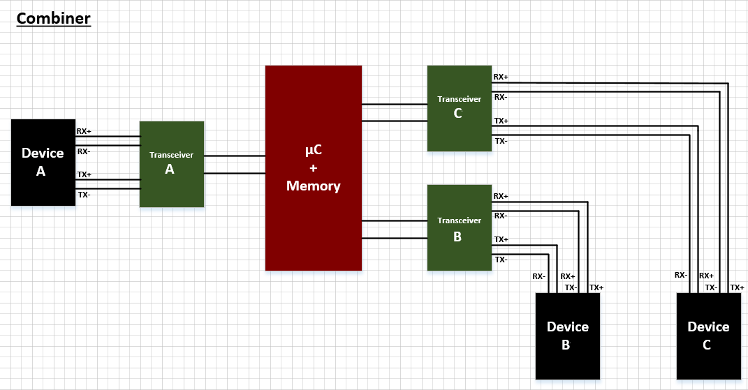
- Combiner: I need to combine signals form device B&C to device A. And here is the problem (there can be only one emitter in RS422)
The questions are: Can I solve this problem putting a microncontroller+memory between device A and device B&C, so I can combine the frames one after the others? Would it affect the splitter side?
Or do I absolutely need to have two separate networks: - One "splitter" network between 3 independant devices (A to B&C)? - One "combiner" network between 3 other independant devices (B'&C' to A')?
And what about the termination resistors?
My mind is not really clear about it. Thank you for any advices/tips.
The RS-422 standard is intended for multi-drop applications consisting of one transmitter and up to 10 receivers on a given line, so if you are thinking of a topology involving multiple transmitters or bi-directional communication it would be outside the scope of 422. It could still be made to work, but it may be tricky - termination for these kinds of networks would typically need to be placed at both ends (since either side could transmit or receiver), but in doing that the effective load resistance seen by the RS-422 driver would drop below what it is likely specified for.
Have you considered switching to RS-485? It is a similar standard, but was developed with the intention of handling these kinds of bi-directional/multi-point topologies that aren't cleanly serviced by RS-422. If you had some mechanism for making sure nodes B and C didn't transmit at the same time, then you could then have all the nodes sharing a common bus. If not, then you could still use the "combiner" as described to arbitrate between the two colliding transmitters but you may be able to simplify the connections between A/B/C/Combiner by making the links bi-directional and terminating at both ends.