This thread has been locked.

If you have a related question, please click the "Ask a related question" button in the top right corner. The newly created question will be automatically linked to this question.

Reccomended Schematic for SN65HVD233-Q1

Other Parts Discussed in Thread: SN65HVD233-Q1

Dear, Sir.

My custommer try to use SN65HVD233-Q1 as CAN PHY. Unfortunately, CAN Bus application

is first time for them, so they are requesting the recommended schematic & component for it.

I founf the user's guide, SLLU234.

I would like to make sure as below. Please help us.

1. All component value is not defined on the guide.

    It is possible to clarify that?

2. R11/R12 Termination.

   I wonder  these terminations are needed to connect active system CAN Bus?

3. TXD & RXD.

   I wonder the series resistors, pull-up resistors & capacitors  are needed?

4. Choke coil & TVS.

   Is it possible to clarify recommended part number or spec?

Best Regards,

H. Sakai

  • Hi Sakai,

    1. All component value is not defined on the guide, It is possible to clarify that?

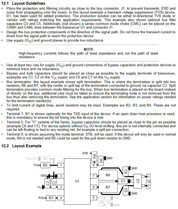
    a. Layout guideline from the TCAN1042 datasheet is below. This should provide a clear guide for you. Typically decoupling caps are 0.1uF and pull up/down resistors range from 1k-10k depending on how hard the pull needs to be. Please see the SN65HVD233-Q1 datasheet for more information about CAN.

    2. R11/R12 Termination, I wonder  these terminations are needed to connect active system CAN Bus?

    a. CAN is a multi-point bus topology which means there are multiple drivers and receivers attached to the same bus. Typically only the two farthest ends of the bus are termination and the rest is left terminated. Please follow this link for more information on CAN: https://e2e.ti.com/tags/CAN+blog+series

    3. TXD & RXD, I wonder the series resistors, pull-up resistors & capacitors  are needed?

    a. Series resistors are not required on TXD or RXD, these are only current limiting resistors to protect the device from an over current condition. A cap to ground may be used on both TXD and RXD to help filter the signals to and from the uC/uP. TXD may require a pull up resistor if the uC/uP is open drain.

    4. Choke coil & TVS

    a. TVS diodes can be placed on the bus pins for extra external protection above and beyond what the SN65HVD233-Q1 already supports. Please see the ESD section of the SN65HVD233-Q1 datasheet for information on the levels that the CAN devices protects to.

    b. Common mode chokes are used to suppress the amount of radiated energy that is coming from the bus pins.

    Please let me know what other questions you have and I will be glad to help!