This thread has been locked.

If you have a related question, please click the "Ask a related question" button in the top right corner. The newly created question will be automatically linked to this question.

TUSB2036: TUSB2036 device descriptor failure

Part Number: TUSB2036

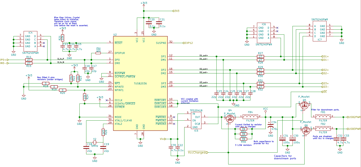
I inserted a TUSB2036 USB hub into my design. It is statically connected to a FTDI USB to UART chip and has the other two ports available as USB connectors. Port number three is disabled by pulling NP3# high. The design is on a 4 layer PCB, all differential traces are length matched, all differential traces have the 3W rule applied to them, and the board is impedance controlled +-15%.

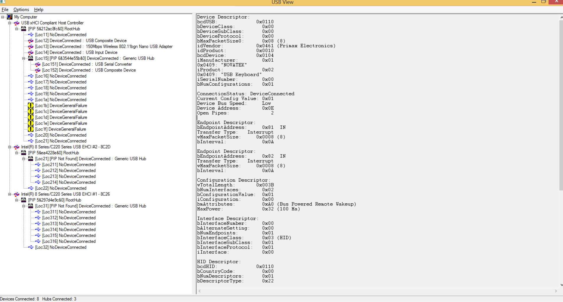
I have programmed the microcontroller and I am using it to communicate with the computer and all works as it should. I have furthermore tested the USB port that I have available with numerous devices, including a mouse, a keyboard (HID devices), and an Arduino. All of that works fine and I am able to get communications working between the computer and those devices.

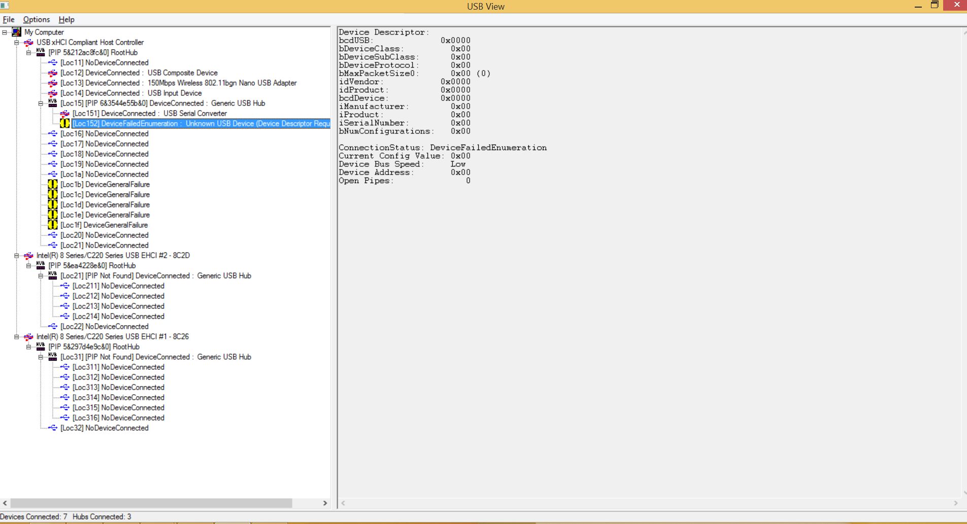
However, the intended device that I want it to interface with is a camera, the problem I am having is that Windows puts the device into suspend mode as the device descriptor request failed. I tried a few different cameras and they all had this same issue as well as a different USB hub (purchased as an off the shelf USB hub product) all of those resulted in the same. Plugging the intended camera through the off the shelf hub enumerates it as it should. All of the devices that get this error work when plugged directly into the computer as well.

All I could find in the datasheet of the TUSB2036 about descriptors and vendor IDs was under section 8.4.2 which I take to be about the hub's vendor ID. 

I have not worked a lot with USB and this was the first time I included a USB hub in my design. I hope someone can help me out troubleshooting this.

  • Hello Atli, 

    Would it be possible for you to share a protocol analyzer capture when connecting the failing device ?(1. Host-Hub, 2. Hub-Device).

    Please, also share your schematics, so we can double check the device set up. 

    Have you tried connecting the Hub and the downstream devices to a different OS? 

    Regards

  • Hello Joel,

    Thank you for your reply. I have attached an image of the schematic for you to look at. As for the power segment in the bottom right corner on the schematic, it is a slow start circuit for the device. It seems that it is only certain USB class devices that I am not able to enumerate properly, HID devices seem to have no issue and neither do USB to serial devices (i.e. the Arduino and the FTDI chip that is on board).

    I have also attached a file with the capture for the Host-Hub below, unfortunately I am not able to get the data from the Hub-Device that easily as the hub is integrated onto an IC and I don't have a device to sniff the packets between. Numbers 20214-20576 of said file should be the communications between the host and the hub when trying to enumerate the camera only. In that file the hub enumeration starts at 19638. 

    https://www.dropbox.com/s/ql1kah0m7jwfuep/usb%20capture.pcapng?dl=0

    As for another operating system, I have not tried this on anything but Windows.

    Thanks again for your assistance. I hope that this information is enough to help you help me, if not then let me know and I will do my best to accommodate.

    Kind regards,

    Atli

  • Please, could someone update me on my request status.
  • Hello Atli, 

    Sorry for our late response. We have some comments on your schematics. 

    All the downstream signals (DP and DM) should be tied to ground with 15K resistors like the pull-downs

    The OVRCUR/ inputs should have a pull-up resistor.  A value of 1.5K is sufficient

    Download the usbview utility to get more information about the hub and device. Select the item in the left window will allow its descriptors to be read in the right window. Could you attach some screen captures? 


  • Hi Joel,

    Thank you for the schematic input, I seem to have overseen the 15k resistors from the datasheet. I had ruled out signal integrity issues using the logic that I can still send data through the hub without problems and therefore the signal should be intact. I can use it to connect HID devices and they work without a glitch, I used it to program an Arduino, and the FTDI chip that is always connected on downstream port 1 works as intended. Do you believe the 15k resistor could be the cause of our problems?

    I am able to retrofit a pullup resistor onto the OVRCUR signal. I was under the impression from the datasheet however that due to the mode it is working in OVRCUR3# would have its pullup resistor connected. This was supported by my measurements of it, as it sits firmly at 3.3V until I connect something which draws more current than the allowed 500mA. I will retrofit a resistor on and test it so that we can cover our basis during the debugging.

    I have included screenshots from USBView with different devices connected to the hub.

    First there is the Hub itself:

    continued image

    Second there is the FTDI chip that is always connected to the hub on port 1:

    Continued image

    Third there is no device connected on port 2:

    Fourth there is the camera that is intended to be used with the device on port 2:

    Fifth there is an Arduino connected to port 2:

    Sixth there is a keyboard connected to port 2:

    continued image 

    I decided to include more information than less to help you better.

    From those images I have an additional question. Based on what is said in 9.1 Application Information in the TUSB2036 datasheet, should the max power (in USBView) of the device not be 500mA as it has finished power up at this point? 

    I hope that these images and explanations help you helping me. I look forward to hearing more information on the matter from you and as before let me know if you need any more information and I will provide it as soon as I am able.

    Kind regards,

    Atli

  • Afterthought:

    I have re-read the datasheet very thoroughly and I believe I have found the root cause of the issue. The camera I am trying to use forces a high speed connection which the hub does not support, it only supports full speed operations. Could someone confirm for me that the symptoms that I have detailed can be caused by this as the root cause. I will follow this up with the manufacturer of the camera to make sure that this is what happens when the camera is connected on a full speed interface.

    I have attached images of the standalone camera connection to support this.

    continued image:

    I look forward to hearing from you.

    Kind regards,

    Atli

  • Hello Atli,

    It seems that you camera is a high-current device. When a high-current device is connected to a bus-power hub, the host will not configure it. You can verify this by changing the BUSPWR pin to high.

    Regards
  • Hello Joel,

    I have tried what you suggested and made the hub think it is self powered. I can see no change in its behaviour with that aside from what can be seen in the following image.

    continued

    The camera still gets the same as before in USB View:

    I did this by connecting the 3v3 supply to the BUSPWR pin. The hub is still powered by the bus but there are safeguards which limit it to draw only 500mA at the most. Currently the hub is in self powered ganged mode which means it should be able to put out 500mA on the two ports. It currently thinks it is supplying 90mA to the FTDI chip and the camera believes it should draw 400mA which is below the 500mA limit.

    Do you have any other ideas about what could be causing this behaviour?

    Kind regards,

    Atli

  • Hello Atli,

    It seems that the driver is not able to enumerate this superspeed camera as a full speed device. According to the USB specification, you must connect a pullup resistor of 1.5 kΩ on D+ for a full-speed device or on D– for a low-speed device, therefore, I would check if there is a pullup in D+ of the downstream port where the camera is connected.

    Have you considered using our TUSB4020 ? This is a two port high speed hub. You can order EVM to test your application.

    Regards
  • Hello Joel,

    I am aware of the 1k5 resistor for the D+. Am I correct in assuming that this should happen only on the client side rather than the host side? I have put this in on my upstream port as specified in the TUSB2036 datasheet (connected to the DP0PUR pin). From a visual check of the camera there doesn't seem to be anything but an ESD device connected to the D+ or D-, I will confirm this with the camera manufacturer.

    I have considered using the TUSB4020 but when this board was designed it was assumed, perhaps wrongfully, that the end device could operate as a full speed device. I am currently querying the camera manufacturer to that end and I will make sure to forward on anything from them that will explain this. I will make sure to order an EVM before I re-spin this board and verify that the USB hub will work with my specific application.

    Thank you for you help. I will let you know if I figure anything else out and make sure to mark an answer if the camera manufacturer's verify this to be the case.

    Kind regards,

    Atli