This thread has been locked.

If you have a related question, please click the "Ask a related question" button in the top right corner. The newly created question will be automatically linked to this question.

TPS65986: Confgiring TPS65986 to sink mode (USB powered only) for 2ch USB + 2ch Display port operation

Part Number: TPS65986

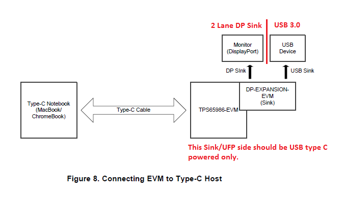
I am now working TPS65986EVM + DP Evaluation EVM and trying to configure this setup for device only operation to connect USB3.0 and 2 lane Display port.

Need your support in understanding how to configure TPS65986 PD controller to sink mode (USB powered only) for 2ch USB + 2ch Display port.
My testing observations with existing configuration ID's are

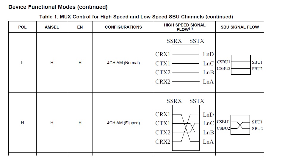
1. CFG ID- 0, 4, 5 -> USB device detected. However this setting looks like 4Lane DP mode as per MUX select lines(AMSEL->H, POL->H/L, EN->H). So I felt USB is detected in USB2.0 mode
2. CFG ID- 1, 2, 3, 6, 7 -> USB device not detected. This setting looks like 2ch USB + 2ch DP mode as per MUX select lines (AMSEL->L, POL->H/L, EN->H)
Note: The logic level of MUX select lines mentioned above are same in all listed CFG ID's.
Please help..
  • The "Multifunction Preferred" bit (in the Display Port Capabilities register) is set to 0 for all configuration IDs in the default TPS65986 booster pack firmware. The result is that 4 lane DP is always negotiated. To enable 2 lane you will must use the TPS6598X Application Customization tool to generate a new firmware image with the Multifunction Preferred bit set. Setting this bit, along with selecting "UFPD Receptacle or DFPD Plug Pin Assignment" values of C and D will allow 2 lane DP + 2 lane USB.

  • Thanks Brad for your inputs.. Can you please also clarify a doubt below relating to questions asked last time and an issue in TPS6598X Application Customization tool,

    From your points it is clear that all configuration ID's are going to support 4Lane DP so USB shall be only 2.0. However in few CFG ID's (ID - 1, 2, 3, 6, 7), the mux select lines is giving out logic levels for 2ch USB + 2ch DP mode (AMSEL->L, POL->H/L, EN->H). So in this case because of Multifucntion bit=0, the entire USB3.0(including USB2.0) is not working. Is my understanding right Brad ?

    Regarding the TPS6598X Application Customization tool usage I am seeing an exception message(as attached) pop-up on selecting TPS65986 device. Can you also help on this issue ? Only after this I can start working on generating a new firmware image with the Multi function Preferred bit set..

  • Yes, until a configuration with the multifunction preferred bit is set, USB may not work. One thing that will also help is to look at the PD negotiations to make sure that DP alternate mode is actually entered. Please use a PD analyzer to look at that.

    As for the problem loading the TPS65986 project, I have not seen that problem. What version of the tool are you using. The latest verison is 2.10. If you are using an earlier version, please download the newest version. You could also uninstall and reinstall the tool. Please install is to a directory that does not require special permissions (administrator, for example). In some instances we have seen problems with that.
  • Thanks Brad for clarifying multi function option.

    I am using TPS6598x Application Customization Tool Version 2.10 only.. I tried re-installing the tool as well but still the error persist..

    This error comes only when I select TPS65986. If I select TPS65982 the project is loading and I am able see the register settings. Please help..

  • 1. How are you opening the tempate, *.tpl, file? Are you using Project->New Project or Project->Load Project? The correct way is to use Project->New Project. I see a similar error message when I try to open it the wrong way.

    2. Please send me a copy of the templatet file you are trying to open. You can find the file in the directory:

    installation path...\TPS6598x Application Customization 2_10\tps6598x-app-customizer\gui\templates

  • Hi Brad,

    Sorry for the delay..

    1. I am using below flow for loading the template file. Attached the screen shot also for your quick reference.

         Project->New Project -> Device filter (TPS65986) -> Port filter (UFP)

    2. The template file I selected is also attached herewith.

    Note: I tried selecting DFP template files also but the error still persist

    TPS65986_Application Tool Error.zip__

    Please advice..

  • Pandiya:

    Thanks for the screen shot. I did not realize that you had a newer version of the config tool. You are using 2.12, I was on 2.10. After I upgraded to the newer tool, I was able to duplicate the problem you report.

    I looked at the tool source files and believe I have found the problem. The TPS65986 template files have an error in them. Attached is the fixed version of the template you are trying to open. To use the fix, unzip the template file and store it in the directory: <installation path>....\TPS6598x Application Customization 2_12\tps6598x-app-customizer\gui\templates. Then, when you filter to look at the TPS65986 templates you will see a new template with "-fix" in the name. This is the fixed template.

    Please give it a try and let me know if it fixes the problem for you.

    TPS65986_HD3SS460_UFP_Full_2_10-fix.zip

  • Thank You Brad, the template is now loading. But I am able to see the "Multi function preferred" bit checked by default and "UFPD Receptacle or DFPD pin assignment selected with C & D by default. Attached the screenshot herewith.

    1. Does it mean I can use the same binary for my configuration ? Is there any other setting to be taken care for our application ?

    2. How can I relate this with Configuration ID's ? At which config ID this mode will work ?

    3. Do I need to change the PP_HV configuration ?

    For your quick reference I am attaching the image of our application.

    Default Config & Application Diagram.zip


  • Only the default demonstration image for the booster pack looks at the switches to deterime what configuration values to use. That demonstration image is made to demostrate performance in a few default configurations. The normal operational firmware does not look at the switches. So, there is no "config ID" once a standard image has been put onto the board.

    The tool helps you generate a new image. The defaults match the power paths on the booster pack. So, if you are continuing to use the booster pack, you can simply use the binary image generated by this template file. If you are starting to use your hardware, you may need adapt a few things to your board.

    It sounds like you are continuing to test using the booster pack. So, just reprogram the flash on it with the image created by the template.

  • Hi Brad,

    I tried generating the "Flash image binary file" through save binary option(refer figure 1 in attachment) using the templates fix shared to me. But when I try to flash the binary file using "TPS6598x Utilities GUI"  tool it fails in 1st step configuring test itself (refer figure 2 in attachment). It show again the Exception Encountered error. I followed the steps given in section 7 of TPS65986_EVM.pdf. However I have still listed below the step I have followed,

    GENERATING BINARY FILE:

    1.  Launched TPS6598x Application Customizer 2_12 tool

    2.  Selected Project -> New project -> TPS65986 -> UFP -> TPS65986_HD3SS460_UFP_Full_2_10-fix.tpl. The project loaded showing default binary file (tps65981_2_6_v0001.11.09.bin) in General settings tab (Shown in figure 3)

    3.  Selected Shared Device settings -> Display port capabilities -> verified Multi-function preferred bit enabled & UFP pin assignment with C & D selected (Shown in figure 4)

    4.  Selected Binary -> Save binary -> given name for "Flash image binary save file name". Click Ok. (Shown in figure 5)

    5.  Got the .bin file created in the specified location

    FLASHING BINARY FILE:

    1.  Launched TPS6598x Utilities GUI  tool

    2.  Selected Configure -> USB to I2C/SPI Adapter -> Aardvark (Shown in figure 2)

    3.  Click "Test Configuration Settings" .  Shown error " (figure 2)

    Exception Encountered during Configure Test

    Aardvark Interface loading Error: No module named aardvark_py"

    Am I missing anything in the steps to be followed. Please correct me if  I am wrong in any steps. Do we need to use both the tools for this flashing ?

    Note : The exception error shared last time was still present if select any other option in tool. Ex: If  I select "Import configuration from device"  the error will be shown.

    With old version tool (TPS6598x App Customization Tool & TPS6598x Host Interface Tools), if you are able to flash the SPI flash as instructed in section 7 of TPS65986_EVM.pdf  then can you please share that setup files. Because right now I cannot verify even generated .bin file working or not. We wanted to test this as quick us possible. Your support would be very much helpful to solve this issue..

    Thanks

    Binary file generation & Flashing Error.zip

  • Please see section 3.1 of the TPS6598X Application-Customization Tool User Guide. Once you install everything that may be need for the config tool, you will have everything needed for the Utilities tool.

  • Hi Brad,

    Hope you doing good..

    As you mentioned I am are able to flash the bin file successfully.. But I am not able to see USB detection. The pendrive connection is not detected with the binary generated by me..I have attached the binary file generated by me for the 2-Lane USB & 2-Lane DP configuration. Can you please help us in checking the binary file ?

    The flashing is done in two method as mentioned below:

    1. Used TPS6598x utility GUI tool to flash the "Low region binary" file through I2C interface (As per section 3.1 of TPS6598x Application Customization tool user guide)

    2. Used Aardvark Flash center tool to flash the "Full Flash image binary" file through SPI interface. (SPI flash chip is directly wired to Aardvark emulator, TPS6598x utility GUI tool is not used)

    Note: Tired using TPS6598x utility GUI tool to flash the "Full Flash image binary" file through SPI interface but it shown the exception error as noted in my previous discussion

    Kindly advice..

    Binary files.zip

  • Please send your project file that corresponds to the binary files you sent. To help use understand more quickly, please give information about whate template you opened when you selected "New Project" and provide a list of all items you changed.
  • Hi Brad,


    Attached the project file along with recent binary & our application concept for your reference. The template I am using for new project is the one shared by you named "TPS65986_HD3SS460_UFP_Full_2_10-fix.tpl". Since the default templates comes along with tool for TPS65986 is showing exception error.

    The changes done are

    1. Multifucntion preferred bit (0x51) -> enabled

    2. UFP_D Pin Assignments Supported (0x51) -> Selected C & D

    3. Port information (0x28) - > Sink/Source. Power Role = Sink. Data Role = UFP. PR_Swap supported, DR_Swap supported.

    TPS65986_DP SINK_USB3.0_NO PR SWAP_PRJT.zip

    Thanks

  • Everything you are doing looks correct. So, I talked to the folks that generated the template and the EVM hardware designer. I found that the GPIO mappings in the template are not correct.I worked with them to create a corrected project file. Please see the attached project file, TPS65986_HD3SS460_UFP_Full_2_10-fix-gpio.pjt. The project file was created by starting with the "_fix" template file I gave you last week. The GPIO mappings in the file have been updated. You can use this project in config tool version 2.12 by using Project -> Load Project.

    TPS65986_HD3SS460_UFP_Full_2_10-fix-gpio.pjt

  • Hi Brad,


    Sorry for such delayed response..My thanks to you for sharing corrected project file.

    The binary from this project file helped us to some extent. Right now with we are able to see the display instantly on power-up but goes off after 2 seconds. Later that there is no display image coming. When we probed on High Speed Mux(HD3SS460) select lines from GPIO's of TPS65986 chip it is in 4 lane DP state(AMSEL->H, POL->H/L, EN->H) as shown in attached image. So it looks like the configuration of 2 Lane DP + 2 Lane USB is not effected in the project or binary file we are testing now. Kindly help.

  • Hi Brad,


    Sorry for sharing false data.. The High Speed Mux(HD3SS460) select lines(AMSEL->L, POL->H/L, EN->H) from GPIO's of TPS65986 chip is proper for 2 Lane DP + 2 Lane USB. But still the we are not seeing the DP signals.


    I have doubt on HPD between Display & TPS65986. Felt like handshaking of Type C source device & DP sink is having issue during negotiation?

    Expecting your suggestion or guidance on this. Please help..

  • Hi Pandiya,

    I have been assigned to your issue and wanted let you know I am working on recreating it. I will update you asap.

    Thanks

  • Hi Jeffrey,

    Thank You for your response.

    Awaiting for your updates..

  • Hi Pandiya,

    While Iam still trying to recreate your issue I wanted to give you a guide on how to enter DP alt mode with the base EVM FW which will work with two tps65986 just to get you up and running with something.

    Please, Let me know if you are able to enter DP mode using this guide attached below. I will update you asap reguarding your issue.

    0638.Testing DP alt mode with base FW image.docx

  • Hi Jeffery,


    Sorry for the delay in responding..


    I have tested this setup already to make sure the boards are working with two tps65986. However the barrel jack is connected to Sink/UFP board only (Right side board) and it was working.


    As per the document shared by you, When I connect the barrel jack on the source/DFP, the Sink/UFP board is not powering ON and no display & no USB working. So my understanding on the default firmware not working in this case is because when sink/UFP board is kept all dip switches to the left (all zero's), this configuration does not support power role of sink (as mentioned in Table 2. TPS65986EVM Configuration Table in TPS65986 EVM User's Guide).

    To brief you about what is my expected firmware setting is please refer the attached picture. Awaiting for your response.


  • Hi Pandiya

    Team has confirmed that DP Alternate mode is fully functional with TPS65986 EVM using EVM recovery firmware image as well as latest released v1.12 firmware image. You can follow Testing DP alt mode with base FW image document that Jeff has posted and let us know if there is any follow up question based on your tests.

    Regards,

    Atiq

  • Hi Atiq,

    We are able to test the same using 2 TPS65986 EVM and it is working. However our use-case is sink only with 2lane DP + USB3.0 as mentioned in my last reply. So I tried connecting the a TPS65986 EVM with sink settings to USB type C host (Mobile phone/Mac Mini) and the sink EVM is restarting continuously. Then if I connect barrel jack to this board, Display(hopefully 4 lane) & USB (hopefully USB2.0) both are working. This is making us to depend on external power in addition to USB power even in SINK only mode. Does it need hardware modification for grounding PP_5V0 & PP_Cable for unused condition?

    Can you please test similar scenario with the default firmware and help in creating the custom firmware if needed to meet the our sink configurations ?

    Query & observation on flashing the recovery firmware:

    1. Why we need to use "tps65982_evm_flash_image.bin" for TPS65986 device
    2. Yesterday evening after re-flashing "tps65982_evm_flash_image.bin", the ‘VERSION’ (0xf)  register says 0x01119 (Byte1 -> 9, Byte2 -> 11, Byte3 -> 1). Is this okay ? Please advice.

    Thanks

  • Hi Pandiya,

    The  "tps65982_evm_flash_image.bin" is supposed to say  "tps659826_evm_flash_image.bin", which is from a inconsistent test case. As for your 2 lanes of DP and USB3, the recovery FW mentioned above will not do 2 lanes (with any combination of dip switch config).  

    The DP pin assignment needs to be 'D' (instead of 'C') in order to be in 2 lanes. I am updating the test document I previously sent which will allow you to enter 2 lane DP/USB3. I will upload when complete.   

    note: In order to get pin assignment D, Multifunction Preferred has to be enabled however there are some connection issues with what I suspect to be from updated graphics driver.  

    Thanks


  • Hi Pandiya,

    I have managed to recreate your 2 lane DP issue using a Macbook as the host and a 86 EVM as the dock. It seems that the GPIOs connecting the SS MUX are incorrectly mapped in the template for this particular test case. This will be updated in the new FW release coming out soon. It will also be cleared up in the 'PD Alternate Mode: DisplayPort' or 'SLVA844A' app note - as well as any other pertinent user guides.

    Testing 2lane DP alt mode with 86 template on 2.15 FW.docx

    Attached is a step by step on how to get 2 lane DP running with one 86 EVM and a Macbook.

    Please let me know if you are able to get 2 lanes working with this setup guide.  

    Thanks!

  • Hi Jeffery,

    Thank you for your continuous support. With the steps you have I have generated the binary. While I test new binary, can you please share your comment for below questions. Your quick support will help us a lot.

    1. How to flash the blank SPI flash(MX25V8035FZUI) for new board ? We are not able to flash it using TPS6598x Utilities GUI tool & App customization tool. This is now totally stopping our testing. Please help in sharing the detailed procedure to flash a blank SPI flash device.

    2. We tried flashing through other evaluation boards also using CCS software. Here flashing is successful but board it not booting (tried connecting same flash to TPS65986 evm also but not working). While flashing the recovery binary, I have given 0x2000 location as offset and it didn't work. Do I need to change the offset or do i need to flash any boot loader/code on 0x0000 location also ?

    3. Can we flash the blank SPI device using I2C interface of TPS65986 device ?

    Regards
  • Hi Pandiya,

    The MX25V8035FZUI is not a supported flash type by 86 and could be incompatible. We recommend using Winbond - W25Q80JVNIQ to flash with the 86.How to flash SPI_86.docx

    However I still included a troublshooting guide for your current test case.

    Thanks

  • Hi Pandiya,

    I hope you were able to get things working. Please let me know if I can further assist.

    Thanks
  • Hi Jeffery,

    Ya it is working but there are some inconsistency issue so we are testing more understand the background of the issue. I will share my observations after completing our planned testing on it.

    Particularly USB3.0 status is connected in TPS65986 data status register but the speed is always in USB2.0 only. Even the USB descriptor says the device detected is USB 2.0 or USB2.1. We are working on why USB3.0 controller connected to his bus is not advertised as USB3.0..Do you have any comments for this issue?

    Thanks much

  • Hi Pandiya,

    Sounds good, please keep me updated.
    The SS MUX - HD3SS460 that is on the DP-expansion board is not capable of Gen 2. The HD3SS460 datasheet states "Compatible with 5 Gbps USB3.1 Gen 1 and AM Including 5.4 Gbps DisplayPort 1.2a".

    If you are needing Gen 2 speed you will also have to also change 'DisplayPort Signaling' in the DisplayPort Capibilities register (0x51). By default the 'DisplayPort Signaling' drop down selection is set to 'DP 1.3' and should be changed to 'USB Gen 2.0' to enable 10Gbps signaling.

    Thanks
  • Hi Jeffery,
    We are expecting only USB3.1 Gen1 (upto 5Gbps)so the existing setting should be okay I guess. 
    On USB3.0 & DP 2 lane testing we are facing inconsistency issue. On our testing we observed that the HPD signal/Interrupt is not transmitted over CC lines on the custom firmware created for USB3.0 & DP 2 lane mode. However HPD transmission over CC lines can be observed all the time with recovery/ default firmware of TPS6598x EVM. Can you support for this issue as well while we continue our testing on the same.
    Regards
    Pandiyarajan
  • Hi Pandiya,

    Sorry for the late reply. We are looking into this issue and will update you asap.

    Thanks
  • Hi Pandiya,

    Sorry for very-very late reply. I am unable to recreate this issue. Were you able to fix this?

    Thanks