This thread has been locked.

If you have a related question, please click the "Ask a related question" button in the top right corner. The newly created question will be automatically linked to this question.

SN65HVD82: Asking for the RS485 SN65HVD82 power over bus HW design and speed recommendation

Part Number: SN65HVD82
Other Parts Discussed in Thread: TPS53319, SN65HVD96

Hi Team,
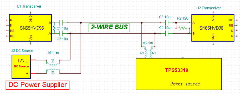
Customer is evaluating SN65HVD82 solution for RS485 power over bus. (www.ti.com/.../tida-00527)
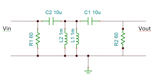
Now customer used 10u and 1mH on the circuit. The power is the 12V from the DC source. TPS53319 Vin connect to the right side.
Please refer to the block diagram in the bottom. Customer test the baud rate for 3MHz and 5MHz. 3MHz is not stable.


Customer has question for the HW design. could you help for the following questions?
1. what is the recommended baud rate on the BUS for stability? 1MHz, 3MHz or 5MHz?
2. What is the recommended inductor and cap value for this design?


Thanks,
SHH

  • Hi,


    One problem I see is that the SN65HVD82 is only rated or a max data rate of 0.25Mpbs so the signal should not be transmitted. The SN65HVD96 can handle data rate up to 5Mbps. Also, how does the TPS53319 fit into this circuit? Is it being powered or supplying the power? 


    1. The baud rate it determined by the single pole high pass filter created by the series cap and half the termination resistance. The higher the pole the more lower frequencies get cutoff. So the higher the frequency the better.

    2. The inductor value should high so that they are seen as a high impedance path for the data signal (XL=jωL). You also need to make sure your inductors have a high enough current rating for the power you need to deliver.

    The capacitor value is determined by the baud rate of the signal. Your customer needs to choose a  capacitor such that the high pass filter cutoff frequency passes the data, and blocks the DC component on the line. Also make sure the series caps have a DC rating above the 12V applied to the bus.

    Another topic in the app note that needs to be made sure of is the that there needs to be very little DC component in your data encoding scheme. The app note recommends a Manchester encoding scheme or something along those lines.

    Regards,

    Daniel Noel

  • Hi Daniel,
    Thanks. Do you have the recommended cap hand inductor value? or the max cap and max inductor value?
    TPS53319 is being power.
    Could you let me know which app note you are referring to?

    Thanks,
    SHH
  • Hi,


    We do not have any specific inductor or capacitor values for this design. All these values depend on the operating frequency, DC bus voltage, and other application specific parameters. That being said, here is an ideal case for this application.

    In an ideal circuit here is what the A/B transmission line would look like this. The 60 Ω resistor is because of the virtual ground with 120Ω termination resistor at either end and the inductors are grounded due to the fact that DC voltage sources look like ground to AC signals.

    And the transfer function of this filter is   

    where:

    L = L1 || L2 = 500 µH

    C = C1 = C2 =10 µF

    R = R1 = R2 = 60 Ω 

    The main concern is for your communication frequency to well above the double complex pole at ‘b’ on the graph above. This pole is mainly dominated by the inductor value   whereas, the pole at ‘a’ is determined by   . Trying to change the capacitors will move both poles, but will move pole ‘a’ “faster” than pole ’b’ because of the square root factor. At 3 MHz you should be fine. 

    Something else you need to keep in mind is the current and voltage rating of the inductors and capacitor respectively. You do not want to exceed the maximum rating this could permanently damage the parts.

    Regards,

    Daniel Noel