This thread has been locked.

If you have a related question, please click the "Ask a related question" button in the top right corner. The newly created question will be automatically linked to this question.

DS90UB929-Q1EVM: DS90UB929 EVM, HDMI working properly confirmation

Part Number: DS90UB929-Q1EVM
Other Parts Discussed in Thread: USB2ANY

Hi,

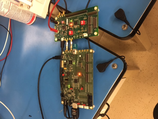
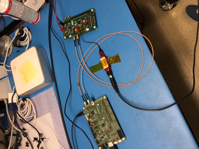
I am using Analog Launch Pad GUI to interface to my DS90UB929 (serializer) --> DS90UB926 (deserializer) boards. I am having trouble detecting the first board on the GUI. After I select the right board from the USB2ANY profile list, I see the correct board with I2C address and board number but I cannot get the HDMI communication to confirm on the GUI. 

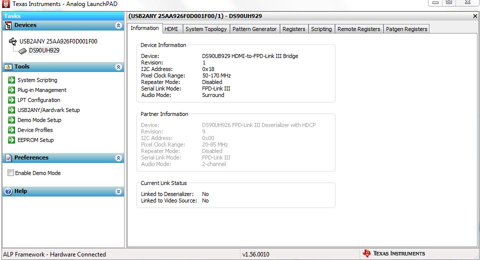
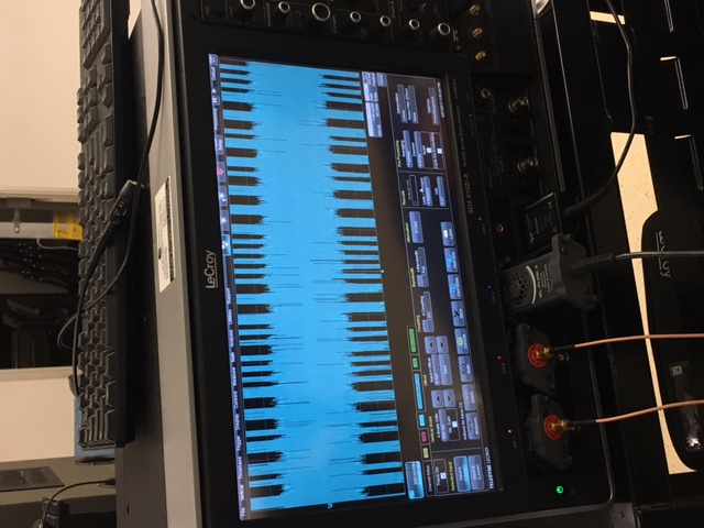
All the settings are default and Hot Plug has been asserted. When I probe the SMA connectors on the output I see bits flipping and data being sent irregardless of having an HDMI input or not. My eye chart looks really good, but I cannot confirm if the HDMI is being sent through, because I see the same thing even when I remove my HDMI cable. Can someone help me confirm if my 929 serializer is working correctly?

  • OK. I got it figured out. I needed to connect the 2 boards and set the registers to their default settings. I used the coax setting on MODE0:1 for the SMA connectors. The reason I was getting no connectivity before is because I soldered a 50Ohm resistor  for R114 and R118 on the 929 board. The 2 boards couldn't talk to each other and input HDMI wasn't being registered for some reason. As soon as I no stuff them and leave the 0Ohm in place for R209 and R210 I noticed a working 929 with 926 EVMs.

    I am now trying to probe the input to my 926 board using a differential probe. My goal is to measure the signal loss in a 10m STP cable between the 2 boards. I will be using a cable made by PIC wire called the E10424. It is a 100Ohm impedence, just like the datasheet recommends. I figure that the SMA connectors are a perfect access point to interface this cable to the boards, so I will hack together some SMA connectors to this cable and wrap the shields to form a conti.

    My problem now is measuring an eye diagram at the RIN+, RIN- of the 926 board. What I get is something like this. I promise I haven't made any modifications to the board and everything is default. Could it be that my 50Ohm interconnects are the source of this noise? And could my 100Ohm cable solve this so I can measure the line loss in? It doesn't make sense why the video works, but I cannot measure an EYE diagram right now. Here's hoping that my 100Ohm cable fixes things.

  • It is unlikely you can obtain accurate measurements on loss and eye based on this setup.
    For eye diagram the recommended method is to monitor the CMLOUT pins for recovered signal. This will have equalized Rx and backchannel removed.
    For cable loss it is recommended to use network analyzer to evaluate the attenuation vs. frequency. Based on your nyquist rate, then you can determine the attenuation in the cable.
    Kind Regards,
    Liam