Because of the holidays, TI E2E™ design support forum responses will be delayed from Dec. 25 through Jan. 2. Thank you for your patience.

This thread has been locked.

If you have a related question, please click the "Ask a related question" button in the top right corner. The newly created question will be automatically linked to this question.

SN65HVD230: Powering SN65HVD230 CAN Xcver at 4.4V to clean up waveforms?

Part Number: SN65HVD230


I have a question on this TI part.  I am running it at 3.3 and the waveforms don’t look great on it.  When I run it at 4.4V it the levels look really good and the signals clean up considerably.


Is it okay to run this part at 4.4?


The data sheet recommends 3.0-3.6 but the absolute max is 6.0V, which I would be well under.


The reason I am using 4.4 is because the output of my battery charger (which powers all my regulators is set for 4.4V and its already on the board that I need to change.

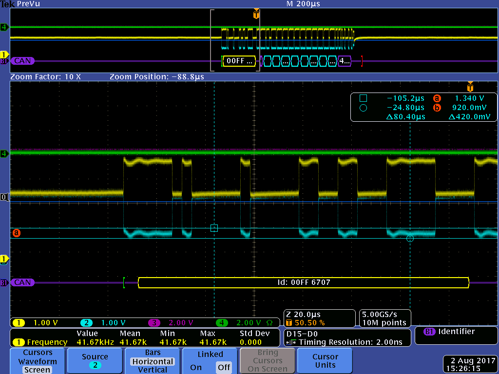
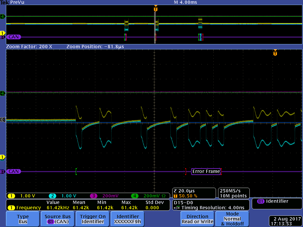
Here are some screenshots for you to look at…


Tek00022.png is at 4.4V and tek00023 is at 3.3V all the surrounding circuitry is exactly the same….


The 3.3V and 5V systems are supposed to be compatible and we aren’t seeing errors, but the waveforms don’t look all that great.


I was thinking of using the SN65HVD running at 4.4V instead of 3.3, according to the datasheet I wouldn’t be exceeding the max Vdd so I wanted to ask.


At 3.3 V there is some hash on CANH and CANL but nothing like there is when I change it to run at 3.3.


This product needs to work on both 3.3V and 5V systems.

  • Adam,

    While I can't recommend you operate the device at VCC = 4.4V since it is outside the voltage range listed in the datasheet, if the device is working correctly at 4.4V, you shouldn't see any problems. That being said, I'd still like to figure out why you're seeing issues at the recommended voltage range. It almost looks like at 3.3V, the supply or driver can't deliver enough current to the bus, therefore when raising the voltage to 4.4V, and lowering the current needed as a result, the driver can fully supply the common mode voltage on the bus.

    The fact that you're still seeing ringing on the CANH and CANL lines even with the 4.4V VCC isn't something that should be happening either. Are there any other components on the bus? Some kind of device that would be introducing capacitance? Looking at the common mode in the 3.3V screenshot, in the recessive state you can see the voltage climbing, and when given more time it gets closer and closer to the correct common mode voltage, as if it's charging a capacitor. It's also important to note that both CANH and CANL in the 3.3V case are lower than they should be, and asymmetrical along the common mode voltage.

    Is there any way you can share a schematic, or a portion of one?

    Regards,
  • Attached is the schematic.  R1 and R5 are No Load.

  • Is there another CAN transceiver on the bus anywhere? The scope shots you provided also kind of look like two different level CANs are competing with each other, and that would explain why 4.4V looks okay while 3.3V doesn't. Your schematic looks fine to me, not too much capacitance on the bus, though sometimes the ESD protection diodes can add excessive capacitance. And the ringing on the dominant edges might be coming from the power supply not being properly filtered, what kind of supply is it?

    Regards,
  • Hi Eric,

    Adam told me I could respond to you here so I figured I might as well. Yes you are correct, we are communicating with a system that is 5V CAN where both transceivers are the MCP2551 powered at 5V.

    The supply is a 3.3V switcher on the main board by Linear tech. I am using the LTC3127 and have it pretty much exactly like they say to do it. It is decoupled with 2 22uf caps on the output and the ripple is very low at the supply.

    The circuit does work with our current system and noone has complained about it, but we were having problems with it working with the old system (the 5V system) as it was causing one of teh nodes to literally fall off the bus. We found it was a SW problem causing the bus to crash but the waveforms don't look great so I wanted to get them to look better. If I put a 60 ohm resistor on my board then theoutput looks perfect, no ringing (or very little) and as soon as I plug it into the system it looks horrible. Having said that, this is on a simulator. Tomorrow I am going to get some scope shots on an actual machine so I see what it looks like on a machine.

    The 5V transceivers on the simulator do not look like this though, and when powered at 4.4 the signal has some ringing on it, but looks so much better.

    Do you know if anyone has interfaced this particular device with the MCP2551?

    Thanks!
  • Brad,

    Thank you very much for all the information. The 3.3V to 5V explains why 3.3V looks like it's trying to climb to a higher voltage and why 4.4V functioned so much better, but you're not actually connected to the system at the moment, just a simulated bus? Is my understanding correct?

    If the ringing disappears when you terminate with a 60 ohm resistance, that points to the transceiver not seeing proper termination when the simulator is connected. I'm interested to see the scope shots with the actual system plugged in, assuming the termination is correct there. And is the simulator simulating a 5V level transceiver? If so, all of what you're seeing makes sense, the two voltage levels are "fighting" with each other, where the 5V comes out the "winner".

    Off the top of my head, no I do not, but I'm sure a customer has in the past. If I can dig anything up and it has useful information, I'll make sure to post it here.

    Regards,