This thread has been locked.
If you have a related question, please click the "Ask a related question" button in the top right corner. The newly created question will be automatically linked to this question.
Hi Team,
I have 2 simple questions regarding .bin file generate function on Application Customization tool.
1. How can we change Pointer address on .bin file when generating it on the tool? Or do I edit the related points for the change?
2. Are there any function to only edit Region1 on the Application Customization tool? Or do I edit the related points for the change?
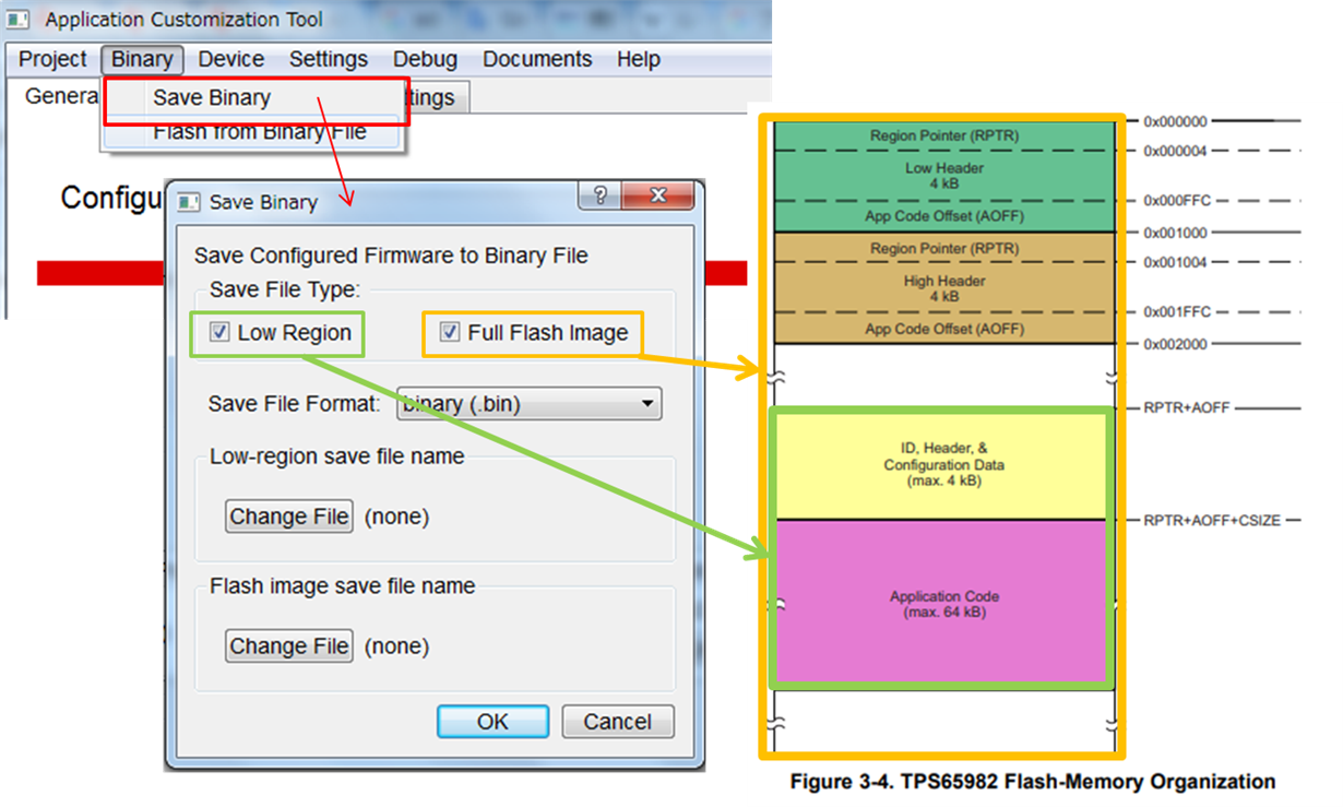
I understand that we can generate 2 kind of .bin file on the tool, one is "App code and its header" only and another is "Full Flash Image" as below.
If there are no functions to only edit Region1 on the tool as answer for my questions above, I need to edit the binary file directory.
Which part must be modified in order to rewrite Region1 properly?
I believe that it is only to rewrite the following two points though, let me confirm if this understanding is correct or not just in case.
1. Region1 Pointer address and header(0x001000~0x002000)
2. Application code and its header(RPTR for Region1 ~ end)
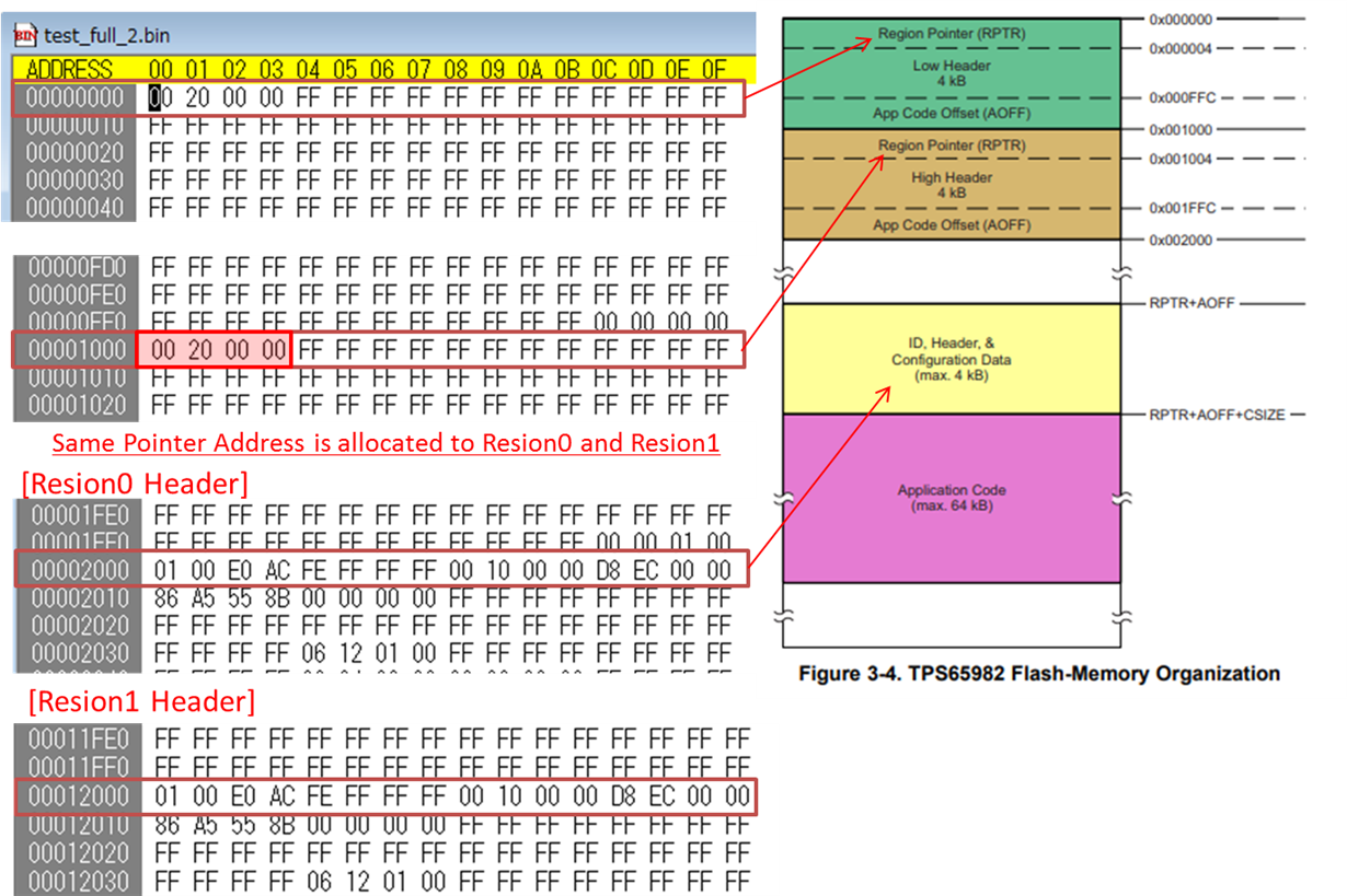
By the way, I think that there is a bug on the bin file generation tool(Region1's pointer address looks same as Region0's one) as below.
Please fix this in next update of the tool.
Regards,
Takashi Onawa
Hi Kumar-san,
Thanks for your quick response on this.
>Why would you want to make this change?
My customer is looking for how to modify Flash memory data. It seems that there was something wrong in their .bin data and they want to update the FW from EC.
There's no bug in the file generation. As you can see in the 'Flash Memory Organization' picture, Region-1 and Region-2 are located at addresses (RPTR-1+AOFF-1) and (RPTR-2+AOFF-2) respectively. RPTR-2 is 0x2000 (same as RPTR-1), but AOFF-2 is different - See 4B @ address location 0x1FFC.
Make sense!. AOFF was always "00 00 00 00" in the document below, so I almost forgot the offset.
Are there any manners in the numbers selection between RPTR and AOFF? eg; RPTR address should be same and so on.
TPS6598x FW Update From Embedded Controller Over I 2C
http://www.tij.co.jp/jp/lit/ug/slvuah7b/slvuah7b.pdf
Also, Could you comment on the question below?
Which part must be modified in order to rewrite Region1 properly?
I believe that it is only to rewrite the following two points though, let me confirm if this understanding is correct or not just in case.
1. Region1 Pointer address and header + AOFF(0x001000~0x002000)
2. Application code and its header(RPTR + AOFF for Region1 ~ end)
Regards,
Takashi Onawa
Hi Kummar-san,
I have a quick question about the address especially Region1.
If they want to set the Region1 app code address to 0x20000, how do we select RPTR and AOFF values?
Different manners are used in the document and our App custom tool. So they can not judge which is better.
TPS6598x FW Update~ document manner :(RPTR:0x00020000, AOFF:0x00000000)
In this document, AOFF value is always 0x0 and changing PRTR value.
App custom tool manner : (RPTR:0x00002000, AOFF:0x0001e000)
On the GUI, PRTR value is always 0x2000 and changing AOFF value.
[BackGround]
My customer would utilize the sample software indicated in the document which you attached. In the document, 0x2000 and 0x20000 are allocated for Region0/1 app code. But the default High region address was changed from 0x20000 to 0x12000 in .bit file generation tool on the latest App Custom Tool, so they want to modify the .bin file generated from the latest App Custom Tool.
Regards,
Takashi Onawa