This thread has been locked.

If you have a related question, please click the "Ask a related question" button in the top right corner. The newly created question will be automatically linked to this question.

SN65HVD1781: Abnormal voltage level of A-B output measured when two transceivers sent Tx simultaneously to RS-485

Part Number: SN65HVD1781

Hi TI,

As the title, we need to figure out why this problem happened in this case. Thanks.

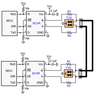
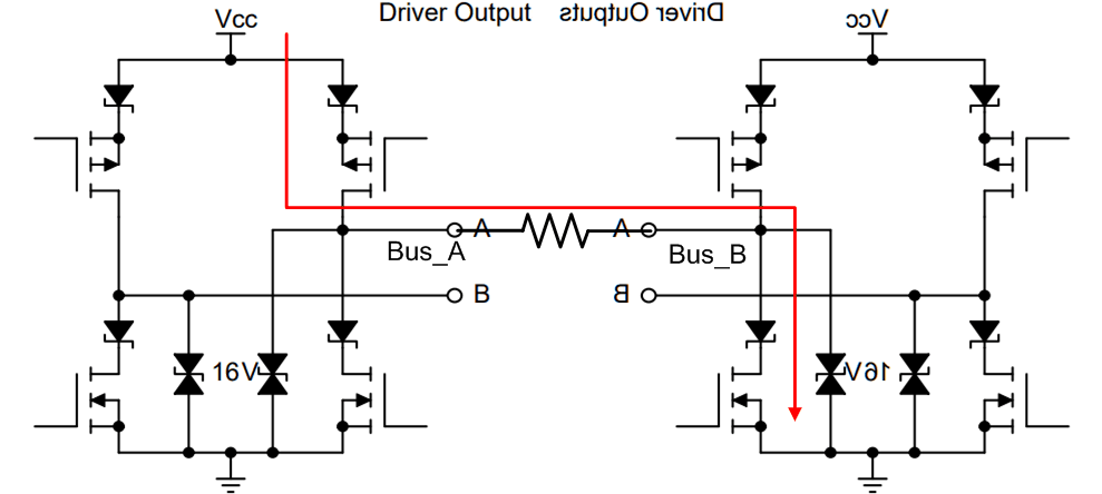
1. System as follow: The length of cable is 300 meters, equivalent line resistance is 27 ohm.

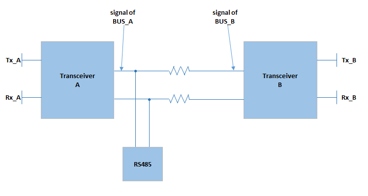
2. Experiment situation: Two transceivers sent Tx simultaneously to RS-485.


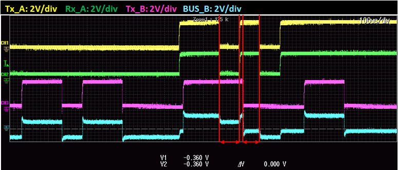
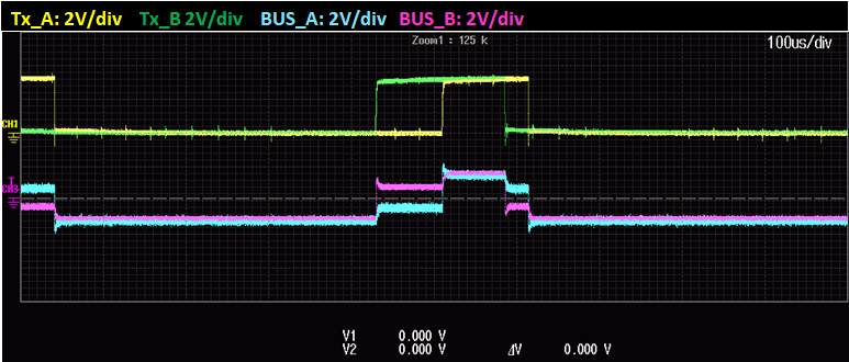
3. Problem: Abnormal voltage level measured while Tx of one transceiver  was high and  the other was low. This problem caused Rx of two transceivers were different.


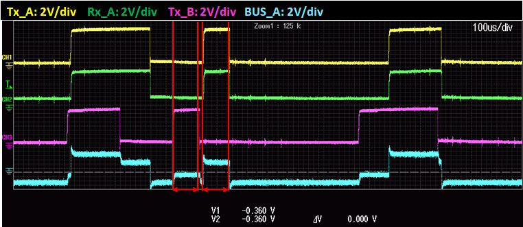
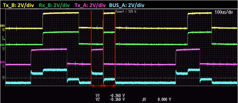
4. Waveform measured: (Tx and Rx signal were measured by passive voltage probe, and BUS signal were measured by differential voltage probe. )

a) Rx_A should be the same logic as BUS_B


b) 

c)

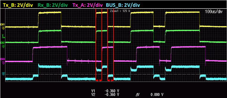
d) Rx_B should be the same logic as BUS_A

e) When the logic of two transceiver were different, the BUS signal went different as well

Regards,

Zach 

  • Zach,

    Thanks for reaching out to us. Could you help confirm some information here? 1) Is the ground of transceiver A and transceiver B connected? 2) What's the supply of both transceivers? 3) Is there any termination resistors on the bus? 4) Is the pin A of transceiver A connected to the pin A of transceiver B? Also pin B to pin B? 5) What is RS485 block? Is it another transceiver or multiple transceivers? Are they full-duplex or half-duplex? 6) Other than RS485 block, are there any other loading on the bus, for example pull up/pull down resistors? I'm looking forward to your feedback.

    Regards,
    Hao
  • Hi Hao,

    1) I used passive voltage probe to measure the Tx/Rx signal of both side, so the ground of transceiver A and B is connected.

    2) The supply is 3.3V.

    3) & 4) The configuration of circuit is as follow:

    R1 & R2 = 3.3 ohm

    so there is no termination resistors on the bus. Pin A/ Pin B of transceiver A is connected to Pin A/ Pin B of transceiver B.

    5) RS-485 block is a USB to RS-485 converter. It collects the data to our communication interface. Differential 2 half-duplex wires (D+, D-).

    6) there are not any other loading on the bus.

    Regards,

    Zach


  • Zach,

    Thanks for your information. Could you please check the pin connection one more time? From your last graph, Tx_A and Tx_B itself generate different polarity on the bus. It looks like when both Tx_A and Tx_B are on, the drivers are fighting over each other and the bus voltage is held in middle. Please let me know if it makes sense.

    Regards,
    Hao
  • Hi Hao,

    Pretty sure that Pin A/B connected to A/B.

    Another information for you, I did this experiment in two cases: (the communication cable was about 1 meter  in these two cases below)


    (1) R1 & R2 were not removed from circuit: 

    The result of (1) is the issue I posted.


    (2) R1 & R2 shorted:

    In this case, the bus voltage will be 0 while the logic of Tx_A is not equal to Tx_B. When the bus voltage is 0, the Rx of both side will receive a low logic.

    Could you please investigate why R1 & R2 exist in circuit or not made the result different? Thanks.


  • TxA TxB BUS_A (Voltage) BUS_B (Voltage)
    State1 Hi Lo
    State2 Lo Hi
    State3 Hi Hi
    State4 Lo Lo

    Zach,

    Thanks for collecting more data. Maybe we could attack the issue by summarizing a table like this. With R1 and R2 populated, we capture the voltage level at BUS_A and BUS_B. Therefore we would know how much current flows through the resistors. Thanks!

    Hao

  • Hi Hao,

    We could review the first graphic:

    There are no R1 and R2 in transceiver block, the abnormal voltage level was caused by the 300 meters communication cable ( 27ohm ).

    We could confirm that the resistance can effect the bus voltage level no matter it is 3.3 or 27 ohm, so I list this table below in 27 ohm's case.

    Tx_A           Tx_B          Bus_A(approximate value)          Bus_B(approximate value)


    State 1       Hi                Lo                         0.6V                                              -0.6V


    State 2       Lo                Hi                        -0.6V                                                0.6V    


    State 3       Hi                 Hi                         1.4V                                                1.4V


    State 4       Lo                Lo                        -1.4V                                               -1.4V 


    Zach

  • Zach,

    Thanks for your data. I understand it's the serial resistor that makes the difference. I assume Bus_A and Bus_B are single ended signal. Do you know why they become negative? From your data, (0.6+0.6)/27=44mA current flows from the active high driver to the active low driver. It looks normal. Like a transceiver with termination, the current flows from p side to the resistor then to the n side. With 54Ohm termination, the Vod on the resistor is about 2V typical. Here you have 27Ohm, therefore voltage is 1.2V about half.

    Please let me know if it make sense to you.

    Regards,

    Hao

  • Hao,

    I think I did not define Bus_A and Bus_B clearly. Bus_A/B signal  is the A-B output of transceiver A/B.

    Please review the issue with this information.

    Thanks,

    Zach

  • Zach,

    Thanks for the clarification. I think my theory still holds. When one side is driving high and other side is low, a voltage delta is generated on the bus resistance. Therefore the receiver of each side sees different input voltage and gives different output state. Please let me know if you have any more questions.

    Regards,
    Hao
  • Hao,

    Sorry for the late reply. I calculated the circuit you posted. I think it makes sense to me.

    Thanks.

    Zach