This thread has been locked.

If you have a related question, please click the "Ask a related question" button in the top right corner. The newly created question will be automatically linked to this question.

DS125DF111: PRBS Generator question

Part Number: DS125DF111
Other Parts Discussed in Thread: SIGCONARCHITECT, DS125DF1610

Hello.

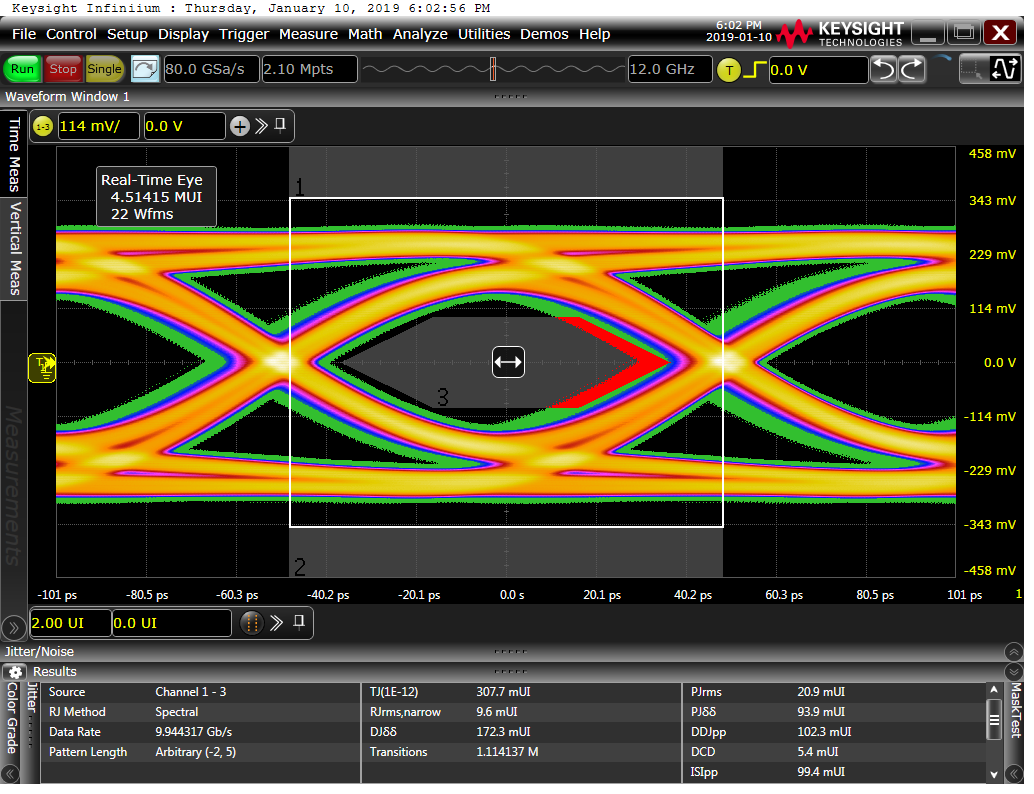
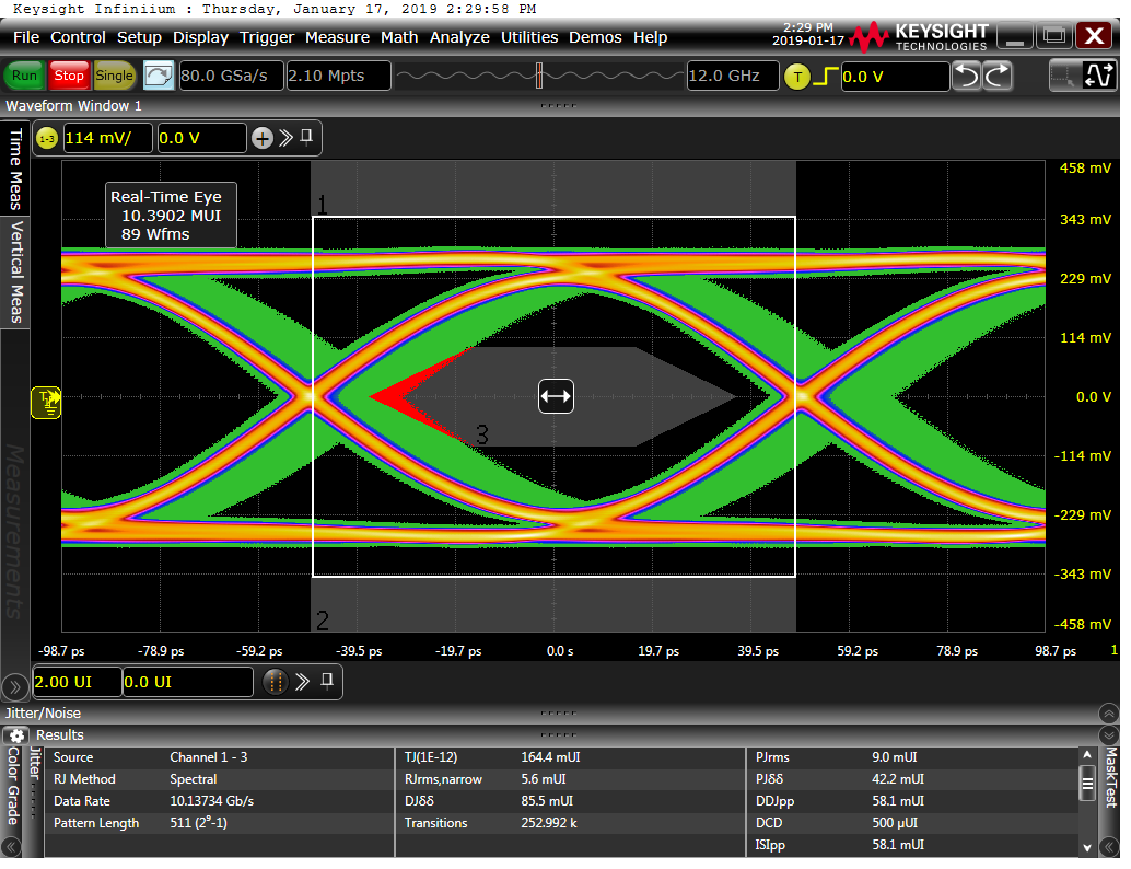
We use DS125DF111 need use PRBS Generator function. But got can not output the 10.3 Gbps problem. Whether it is PRBS 9 or PRBS 31.

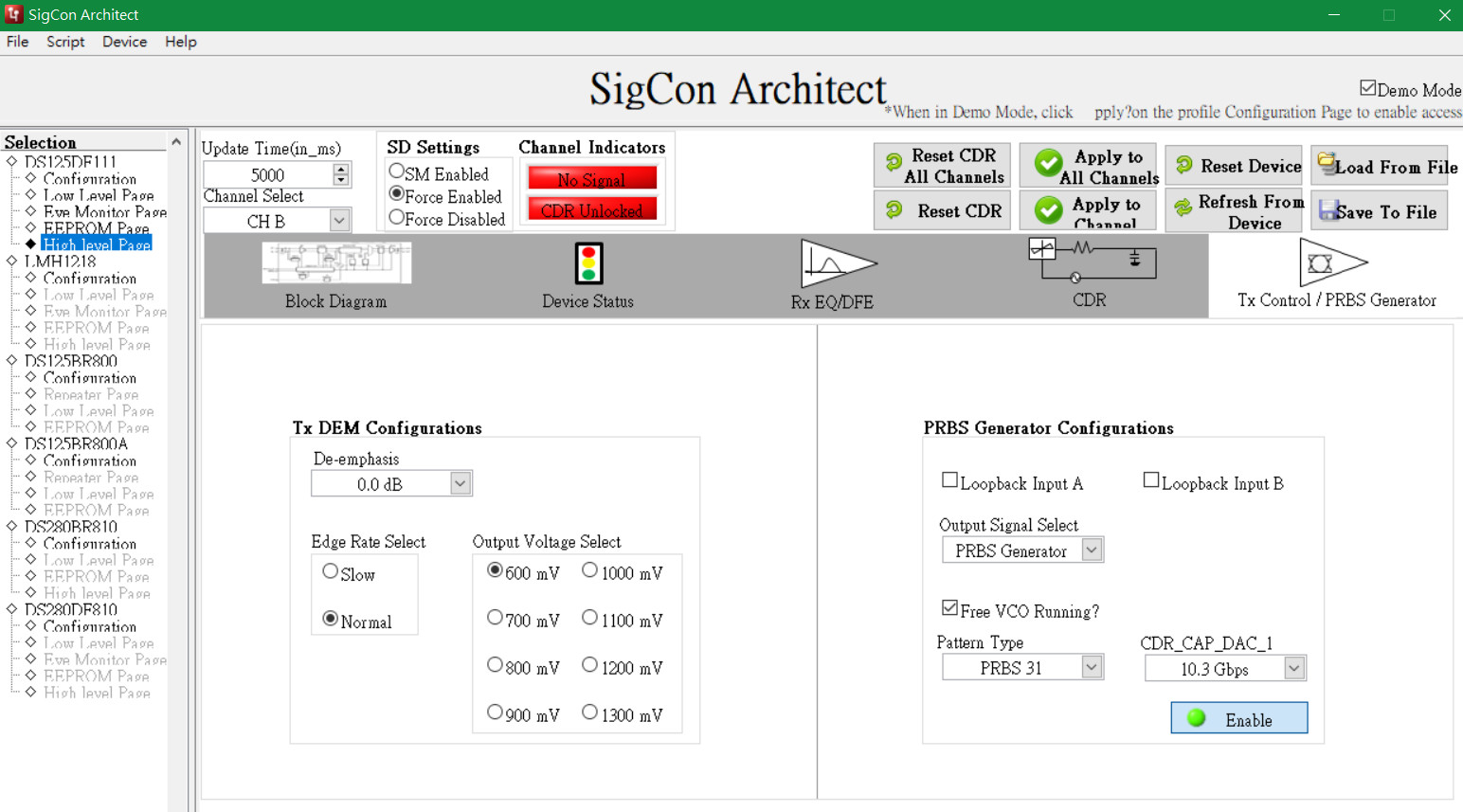
I use Sigcon GUI and try High level page and Low level page(Follow SPEC setting). 

But neither of these methods can achieve the output I want. Is there any other suggestion that I ignored?

The output is very unstable. It is about 9.X Gbps~12.x Gbps. Please refer to the settings below.

DF111 20190110 - 1.cfg

  • DS125DF111 PRBS Gen OUTA.cfgHi AJ,

    I used register settings noted in DS125DF111 data sheet table 20 and was able to generate PRBS from OUTA.

    Using SigconArchitect, let's do the followings:

    1).  Power up the device.

    2). Using SigconArchitect, go to low level register settings.

    3). Click on "Reset Device" in low level page

    4). Click on "Read All" in low level page

    6). Click on "Load Config" and use attached file

    7). At this point, you should be able to see PRBS generated from OUTA.

    Regards,,nasser

  • Daer Nasser.
    Thanks for kindly help. We will try it in the next few days. If any questions will let you know. Thank you~
  • Daer Nasser.

    Good day.

    My output is B. So I am modify your settings like attachments. We have some problems and need your help. Thanks~

    DS125DF111 PRBS Gen OUTB _ Test1.cfg

    1. The output is fixed but still incorrect. We need 10.3125 Gb/s. But the actual output is 10.13 Gb/s. Please refer to the following.

    2. Please help explain why the following video will have jitter at 8 seconds.

  • Greetings,

    Using DS125DF111 VCO in free running mode - the frequency may not be exact. It could vary from part to part, depends on temperature, and supply voltage.

    Please note table 20 of the DS125DF111 data sheet. To change VCO running frequency and run at for example 10.3125Gbps, you should change CHA or CHB Reg 0x08 to a value less than 0x12 - present value. You can experiment with different values. Here are steps you need to follow:
    1). Go to "Low Level Page"
    2). Change/write CHA or CHB Reg 0x08 to a lower value - for example 0x10
    3). Click on "Save Config" and use a new name for this configuration
    4). Power off and on DS125DF111 EVM
    5). Load in the new configuration you just saved
    Now you should be running with a bit higher frequency.

    Regards,,nasser
  • Dear Nasser.
    Good day.
    Thank you for your explanation. But we don't have DS125DF111 EVM. We verified DS125DF111 issue on IPC system. Some processes are not easy to do. Is there any other way?
    May I ask about the second question can share your experience?
  • AJ,

    There is no other way to generate a free-running PRBS.  The frequency is continuously changing as Nasser explaned.  At the 8 second point the oscilloscope issues a warning and updates the display.  The warning is likely due to the frequency output of the DF111 VCO shifting enough to cause issues drawing the eye display.

    Please feel free to ask additional questions about TI products.

    Regards,

    Lee

  • Dear Lee.

    Thank you for your reply.

    I will try on the first question.

    The second problem signal is generated from DF111. Is there a way to solve it? Thank your help~

  • Hi AJ,

    To fix the frequency so your scope could run without this warning, you can lock DS125DF111 to a signal then use the recoverd clock to generate prbs pattern. DS125DF111 data sheet describes register settings for this mode(refer to table 19 register settings in DS125DF111 data sheet).

    Regards,,nasser

  • Dear Nasser.
    Good day.
    I have tried Table 19. but I have not succeeded. Can you provide the .cfg file of OUTB to me. Thank for kindly help~
  • Hi AJ,
    When you made this measurement, did you have a signal on the input of the channel? Was the CDR locked?
    Regards,,nasser
  • Dear Nasser.
    Good day.
    There is no input signal in PRBS generator mode and the CDR is unlocked look from the High Level page of the Signcon GUI.
    Thanks for kindly help~
  • Hi AJ,

    If there is no input signal and CDR is not locked, to enable PRBS generator you MUST use table 20 register settings or use the configuration file that I sent you earlier. In this mode, VCO is free running and output data rate is not accurate and it is not stable.

    To have a stable 10.3125Gbps data rate, you MUST follow table 19. Based on table 19, you should input a 10.3125G signal and CDR must be locked.

    Regards,,nasser

  • Dear Nasser.

    Thank you for your reply.

    May I know why is the description in SPEC output is 10.3Gbps. Thansk for kindly help~

  • Hi AJ,

    Table 20 or free running VCO frequency is not exact. You can change content of register 0x08 to get 10.3Gbps. However, this supply voltage or temperature dependent.

    Please let us know about your application and there could be other ways to provide a fixed 10.3Gbps data stream.

    Regards,,nasser
  • Dear Nasser.
    We are an IPC application. Use the SFP+ connector and generate a 10.3125G signal for test. The system functions are normal. Thanks for kindly help~
  • Hi AJ,

    Thanks for your reply.

    Please take a look at DS125DF1610 device. This device can generate PRBS pattern using integer multiple clock on it's input. Unlike free running VCO, this part uses this reference clock to synchronize. Please note you need to provide a reference clock and I am assuming you have a clock synthesizer to generate this clock.

    Regards,,nasser

  • Dear Nasser.
    Thanks for kindly help. We will try it. Thanks~