This thread has been locked.

If you have a related question, please click the "Ask a related question" button in the top right corner. The newly created question will be automatically linked to this question.

TCAN1051HV-Q1: Yes

Part Number: TCAN1051HV-Q1
Other Parts Discussed in Thread: TCAN1051, TCAN1051HV, STRIKE, LM5060, LM5008, LM5116

1. Do you have a comparison data for transmission performance or EMC of TCAN1051 with and without common mode choke?

2. For TCAN1051HV : External ESD Diodes(CDSOT23-T24CAN) are not required as those can only break at 30-40V whereas IC can withstand 60-70V ; Right ??

  • Rami,

    1. If you click my username, you can find my email information. Through email, I can send you EMC performance of the TCAN1051.
    2. They are technically not required, but recommended in most applications. ESD diodes are meant to protect against the high voltage (up to 16kV in some cases) fast transients that could damage device pins in the event of a strike. You are correct in that that pins are rated for high voltage, but this is for long-term exposure. When a 8kV or higher ESD strike happens, the ESD diodes can react quickly and divert the extra current to GND instead of directly into the device through the pin.

    Please let me know if you have any other questions or concerns.

    Regards,

  • thanks for the reply Erik.

    i have few more questions on the same IC

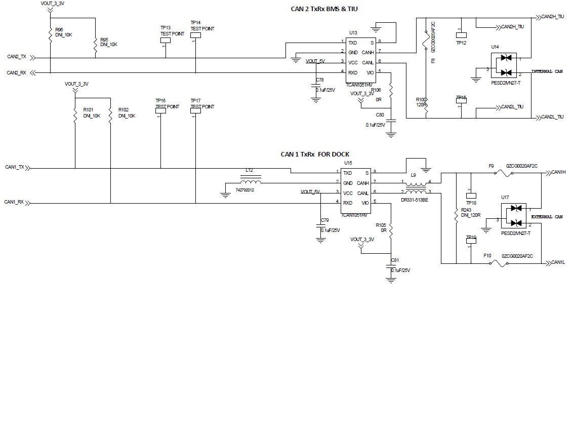
    3. i am using 2 can transceivers (TCAN1051HV) in my 48V battery pack.

    one is connected to vehicle/cherger.

    other one is connected to the other ECU which is inside the battery pack.

    Please refer the block diagram shared .

    the one which is connected to external CAN is getting damaged every time. observed even internal CAN IC got damaged. but failure occurance is more on External CAN. 

    in every failure i observed voltgae on CAN H and CANL found oV to 0.7V constant always.

    can you please suggest me the possible Root cause for the failure

     WBP CAN interface.pdf 

  • Rami,

    It sounds like there is damage on the CANH and CANL bus pins due to electrical over-stress. The fact that CANH and CANL are both constantly at 0 - 0.7V indicates that there is a leakage path to GND inside hte device, and this is typically seen after an ESD strike or voltage transient damages the pins. I see there are ESD diodes and PTC fuses protecting the CAN bus lines though, so maybe the damage is occurring elsewhere and creating a leakage path on the bus pins internally.

    Do you notice the damage happening after a certain condition or event occurs in your application, or is it random? What is the state of the PTC fuses when the damage occurs on the TCAN1051? And is the connector shown in the block diagram ever removed while the devices are powered on and functioning?

    Regards,

  • Sorry my schematic is old. Fuse is not PTC its Fast acting 125mA rated fuse. Designed for PTC only but We have put Fast acting just to understand nature of problems. Fuse never seen damaged during the above mentioned CAN TRANSCEIVER failure.

    Our battery pack is *swapping technology * type.. So for every Drive and Every Charge customer/driver will connect and disconnect the EXTERNAL CAN connector which is also having main power and auxiliary supply

    I'm very new to automotive design environment As well as CAN based products development, Please let me know if I miss something/made mistake in the design which is results into device failure.

    Failures also random only.

    This is our corporate video.. You can see the battery how we are using.  

  • During Swapping(connector removal or insertion) always main power is OFF which is in oftware control through our TI LM5060 high side gate driver.
    But auxiliary supply 12v and CAN remains functional during removal/insertion.
  • Rami,

    Thank you for the information. If the fuses aren't damaged in any way, the damage may also be occurring on the VCC pin. I wanted to know if there was a pattern in case the damage was happening while the CAN messages were going, or if it was in an idle state.

    Does the 12V supply the DC-DC converter? Or what portion of the circuit does the 12V supply? And when the main power is off, are all of the ICs left unpowered as well?

    Regards,
  • One thing reported is; during Swapping its getting damaged (few cases reported like this.

    But I'm not sure about the above mentioned is cause or not. Because person able to see the functioning of battery pack after swap only.

    But tried stimulating this one by doing 3k+ swaps by connecting oscilloscope to CANH, CANL lines ; found ok)

    We used to take impedance of each pin wrt Vcc and ground. Vcc to ground never observed Short/low resistance.

    Power supply : Have 2 DC DC CONVERTER designed directly from 48v battery pack

    1. LM5008 : 48V input to 5V output.. 5v output to 3.3 V Lm1117-3.3 Connected to various sections including MCU and CAN TRANSCEIVER

    2. LM5116 : 48V input to 12v output

    Which is connected to other ECUs like TIU and DIU as shown in previous block diagram.

    when the main power is off (MOSFET control Through LM5060) , are all of the ICs will be in ON condition only.

  • Rami,

    My thought was that quickly removing and introducing different loads could cause voltage spikes on the 12V supply as well as the CANH and CANL lines.

    Were you able to see shorts on any other pins when checking impedance? And is there damage occurring to any other ICs in the system? And the damage that is happened to the CAN transceivers, is the result the same on both external and internal CAN transceivers?

    Regards,
  • My thought was that quickly removing and introducing different loads could cause voltage spikes on the 12V supply as well as the CANH and CANL lines. 

    above we simulated but we didnt observed any spikes. we have done 2k+ swaps by connecting DSO. Loads will be enabled after swap only. so during removing and insertion load will not be there.

    Were you able to see shorts on any other pins when checking impedance? And is there damage occurring to any other ICs in the system? And the damage that is happened to the CAN transceivers, is the result the same on both external and internal CAN transceivers?

    no i didnt observed any shorts. No other Ics damaged during that. most of the cases ext can transcievrs found damaged. 

  • Rami,

    Understood, it still sounds like some kind of electrical overstress. And it's possible that the oscilloscope just isn't catching the transients that happen on that CAN bus.

    • When the transceiver gets damaged, do the CAN lines show any kind of message or is it just steady-state 0-0.7V on both CANH and CANL?
    • If R243 is unpopulated does the damage still occur?
    • I know pin 8 is shorted to GND, but can that pin be monitored while these tests are run and damage occurs?

    Regards,

  • Rami,

    One other thing, have the TVS diodes been checked for damage as well when damage occurs?

    Regards,
    • When the transceiver gets damaged, do the CAN lines show any kind of message or is it just steady-state 0-0.7V on both CANH and CANL?
      • its just steady-state 0-0.7V on both CANH and CANL
      • now i am in visit of delhi field trials for understanding the root cause. i observed 3 failures from last 3 days. CAN TRANSCEIVER DAMAGED during just inserting the battery into vehicle/station.
    • If R243 is unpopulated does the damage still occur?
      • R243 is un populated only in our system. our system will not work if we put 120 ohm in that location.
    • I know pin 8 is shorted to GND, but can that pin be monitored while these tests are run and damage occurs?

    we monitored 5V and 3.3V of CAN TRANSCEIVER with respect to main ground and pin8 and pin2. problem not repeated during our testing with DSO

  • Rami,

    Let me know if you find anything else out in the field trials.

    Since the CAN bus is getting pulled low, I still think there is some kind of electrical over-stress that is damaging the bus pins. This may be hard to capture on the oscilloscope as a voltage spike, and in fact that probe may be affecting the damage from occurring at all.

    The fact that the problem did not occur while monitoring with a DSO is very interesting, do you know how much effective capacitance the DSO probes add when monitoring? And if possible, can you remove the choke from the CAN bus to see if this is affecting anything?

    Regards,