This thread has been locked.
If you have a related question, please click the "Ask a related question" button in the top right corner. The newly created question will be automatically linked to this question.
Hi team,
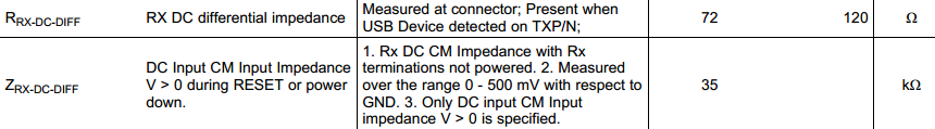
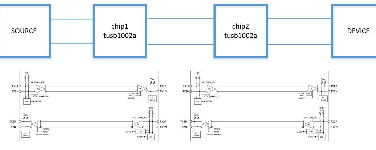
I have questions about the RX impedance of TUSB1002A
- What is the different between the RRX-DC-DIFF and ZRX-DC-DIFF ?
- What is the default of input impedance when power-up?
- How can we design two values of input impedance: RRX-DC-DIFF and ZRX-DC-DIFF on one input terminal?
- If both host and device are in high input impedance when power-up, how they can detect each other?
Thanks and best regards,
Chau Nguyen
Thanks David,
If I use two TUSB1002A in series, how they can detect each other? I mean at first, after power on the chip, the input impedance of two chip are Zrx-dc-diff >=35 KOhm, how they can detect?
Thanks David,
It means when TX2 of chip 1 detect the low-impedance (Rrx-dc) of source's termination, chip 1 will enable the low-impedance at RX1 and RX2; when TX1 of chip 2 detect the low-impedance (Rrx-dc) of device's termination chip 2 will enable the low-impedance at RX1 and RX2. So they can detect each other!
Thanks David,
When power-on,
+ TX2 on chip1 will detect low impedance on Host RX, then enable chip1 RX2 RRX-DC
+ Tx2 on chip2 will detect low impedance on chip1 RX2, then enable chip2 RX2 RRX-DC
+ TX on Device will detect low impedance on chip2 RX2, then enable its RX RRX-DC
+ Tx1 on chip2 will detect low impedance on Device RX, then enable chip2 RX1 RRX-DC
+ Tx1 on chip1 will detect low impedance on chip2 RX1, then enable chip1 RX1 RRX-DC
+ Finally, the host can dectect low impedance on chip1 RX1.
Is that right?