This thread has been locked.

If you have a related question, please click the "Ask a related question" button in the top right corner. The newly created question will be automatically linked to this question.

DS125DF111EVM: How can make the DS125DF111EVM work normally in Pin Control Mode?

Part Number: DS125DF111EVM
Other Parts Discussed in Thread: DS125DF111

We set all the jumpers according the description of DS125DF111EVM Evaluation Board User's Guide 5.1.1 but we can not measure any output waveform in OUTB pin when the signal source input the INB pin.

We measure that the voltage of VODB pin is about 100mV with multimeter.Is the voltage normal?The voltage of VIN,VDD,REFCLK_IN is normal and the voltage of OUTB- is 0V.

We suspect the DS125DF111 is not working during the testing process.

We want to know what need be set to Pin Control Mode except the jumpers setting,such as some register of DS125DF111 need to be set or other signal need input the EVM.

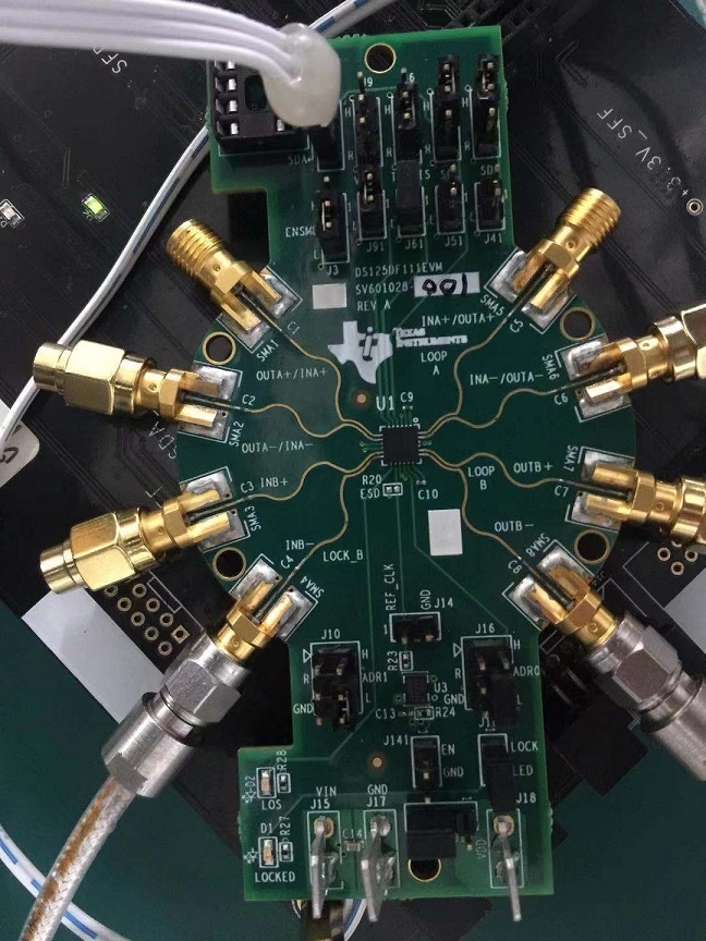
Our jumpers setting picture is below:

  • Hi,

    What is the current drawn by the 3.3V power supply?

    What type of signal are you using as an input?  There is only one cable connected.

    What is the data rate of the input signal?

    If the DS125DF111 is not locked to the incoming signal the output will be muted.

    Regards,

    Lee

  • The currentdrawn by the 3.3V power supply is about 100~150mA.

    The signal source is PRBS31 and the data rate is 10.3125G.

    The LOCK LED don't light green.

    We Try to connect A&B channel with the signal source,but the EVM still have no output signal or voltage.

  • Hi Harrison,

    The DS125DF111 will need to be programmed to lock to 10.3125 Gbps.  The default datarate for this device is 9.8304 Gbps.

    With the default datarate applied the device will lock to the data.  Only when the device is locked with there be an output signal.

    Regards,

    Lee