This thread has been locked.

If you have a related question, please click the "Ask a related question" button in the top right corner. The newly created question will be automatically linked to this question.

TCAN1051-Q1: How to measure TCAN1051 Bus driver symmetry?

Part Number: TCAN1051-Q1
Other Parts Discussed in Thread: TCAN1051

Hi Sir,

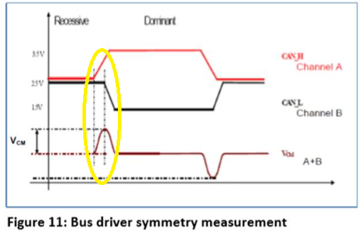
Could you please help to clarify how to measure the Vcm of TCAN1051 Bus driver symmetry?

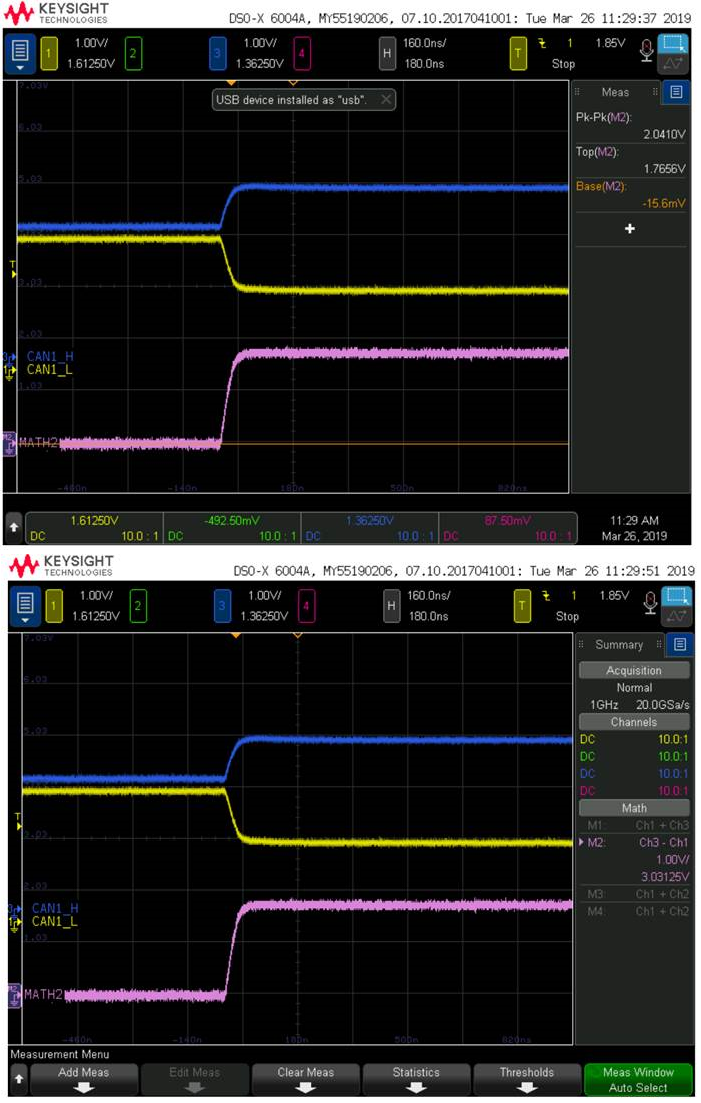
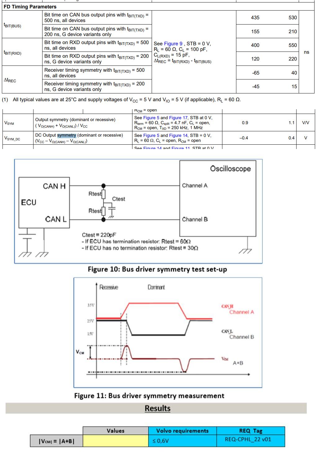
We had measure as below waveform, please help us to check waveform is correct for Bus driver symmetry or not?

Thanks


  • Hi Anne,

    It looks like your oscilloscope's math function is subtracting CANL from CANH in order to give the differential-mode component of the signal. In the spec you copied above, though, it asks for "VCM" to be measured by adding CANL and CANH together. (This will give you a result that is actually 2x the common-mode component of the CAN bus signals.) Then, you can measure the maximum deviation of this "VCM" waveform from its steady-state value (which should be close to VCC).

    Please let me know if this is not clear or if you have further questions.

    Regards,
    Max
  • Hi Max,

    How about signal timing as below diagram yellow circle,
    From this spec., CAN_H asserted early than CAN_L.
    But we measured at same time.

    Is it good if  CAN_H &  CAN_L asserted as same as possible, am I correct?

  • Anne,

    Yes, ideally the CANH and CANL signals would transition simultaneously in order to remain symmetrical. However, no device is truly ideal and so realistically there may be some mismatch. This spec is intended to put a bound on the degree of mismatch. What is shown in your figure above would be very extreme, but I think it is just exaggerated help explain the measurement.

    Max