A related question is a question created from another question. When the related question is created, it will be automatically linked to the original question.
If you have a related question, please click the "Ask a related question" button in the top right corner. The newly created question will be automatically linked to this question.
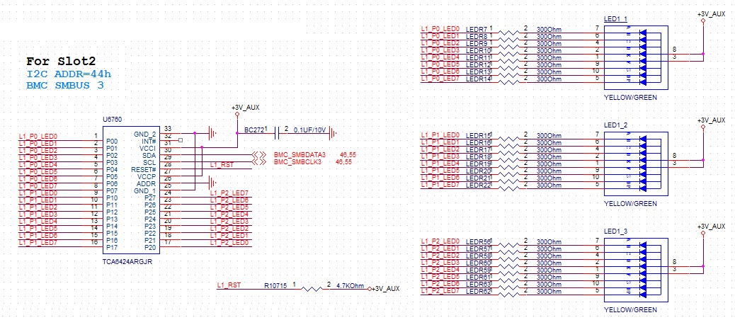
TCA6424A: Schematic review request for TCA6424A with 3 PCS 7-seg LED application
From what I can see, there are no major issues. (Int Pin is floating but that's okay)
Some small points:
1) I2C addresses are 7 bit based and where bit 0 of the overall byte is for the read/write bit so address 0x44h is technically wrong. I2C address with your current configuration would actually be 22h. (010 0010 +w/r)
2) May I ask what the end equipment/application is? My reason for asking is because some applications care about power consumption and section 9.1.1 of the datasheet points out consumption currents can be minimized by adding parallel pull up resistors to prevent shoot through currents when the device (TCA6424A) is acting as an input. If you set the device to be an output high (rather than HI-Z input) to turn off the LED then this would also be a work around to insure consumption current in minimized.
1. The I2C addresses 0x44h were 8-bit setting for our internal request.
2. For part of application , we counter the PCIE slots were be plug in and plug out, and show the results on MB. BIOS or BMC send the I2C command to TCA6424 and light up the LED. , The LED maybe light up when TCA6424A acting as input before BMC initial ready when system AC power on. it's could be acceptable.