This thread has been locked.

If you have a related question, please click the "Ask a related question" button in the top right corner. The newly created question will be automatically linked to this question.

TCA4311A: About SDA,SCAl pin

Part Number: TCA4311A

Dear all,

Our customer would like to know about SDA, SCL pin in TCA4311A and LP5211.

Please answer 2 questions below.

1.Could you tell us if there is a protective element such as a zener diode (ESD pwotective elements) between SDA or SCL pin and GND in P5521 and TCA4311A?

2.

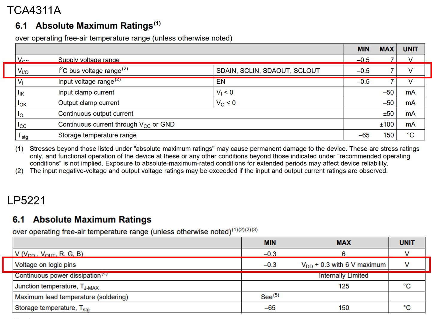
Are the figures enclosed in the red box shown above the figures based on GND?
For example, if the potential of Vcc = 6 V and GND is 10 V in TCA4311A, will the actual range of Voltage of logic pins be 9.7 V to 16.3 V?

It would be great if you could let me know your thoughts on the following questions.

Best regards,
Y. Ottey

  • Hello Y. Ottey,

    I can speak on the TCA4311A standpoint.

    1) TCA4311A does use ESD protection. We do have diodes that will conduct if the device is biased a particular way. (I believe this is what you are asking about). We do not use zener diodes though.

    2) From my understanding, because you are setting the GND of the pin to 10V, the reference point is now higher. This means if you apply 6V to Vcc, then you will have a -4V difference between the two. This negative voltage reference will cause the diodes of the ESD cells to conduct and because there is no current limit (low impedance path) between the two reference points, the diode will likely break and you will damage the device.

    Thanks,

    -Bobby

  • Hi Boddy.

    Thank you for your reply.

    Regarding 2), what about the case of Vcc = 16 V?

    Will Votage on logic pins go from 9.7 V to 16.3 V when Vcc = 16 V and GND is 10 V?

    Also, with TCA4311A, when GND is 10V, does the absolute maximum rating of the actual I2C bus voltage range be 9.5V to 17V?

    Regards,

    Y.Ottey

  • Y.Ottey,

    What you are asking for is a bit risky because you must insure the signals do not go outside the reference ranges otherwise they will break, this includes transient voltage swings.

    If 10V is your reference voltage then the absolute maximum I/O voltages will be between 9.5V to 17V. In theory you can do this but like I said, you must ensure all voltages do not fall outside the limits otherwise damage could occur.

    Yes, you could technically make this work.....

    -Bobby